You can do this by driving directly from the 2 anodes of a push pull tetrode/pentode amplifier without feedback. This will have a high output resistance but might still not be enough for significant electric damping.What if we use a Direct Drive amplifier (without any transformer), then there won't be any conductive path to shuttle the charges from a stator to another. How will it electrically damp the diaphragm velocity? So there's no electrical damping when we use Direct Drive amp for ESL?
But why do you want more damping? Even a 3m x 3m ESL needs LESS damping if it is to be flat below 100Hz
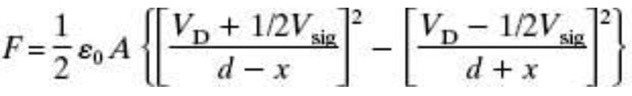
Force and damping are 2 different things. The Force is as Baxandall & bolstert's eqns. This pushes on the load which includes the air, diaphragm, damping etc.In the chapter of Borwick's book for Electrostatic (by Baxandall). In sections 3.2.2 and 3.2.3. He derived the force on the membrane (for Constant Charge), Eq. 3.12., does this Force formula already include/accounted for the mechanical damping in your post #237 above?
Is Borwick's book (or at least the ESL chapter) available on the internet for beach bums who have no money?
The heavy lifting for EQing the ESL-63 bottom octaves flat comes from kicking in the two “bass” panels at lower frequencies. The ESL-63(like the ESL-57) does use under damped fundamental resonance to help extend the flat response an additional half octave, but a Q of about 2.5 is needed (ie not seriously under damped) so significant acoustic damping is required to achieve it by way of cloth mesh attached to rear stator....Actually a 'diaphragm in free air' the size of ESL 63 needs fairly substantial bass boost and this is done by seriously under damping the 'fundamental resonance' ... so there's some heavy serendipity going on 🙂
Some more discussion and plots here: https://www.diyaudio.com/community/threads/full-range-electrostatic-question.256993/post-3965195
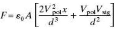
The 2nd term in the Force formula has the transduction coefficient ∝ built into it. Damping isn’t part of the force equation; rather it results from the electrical and mechanical domains communicating with each other thru the transducer motor. An applied voltage results in force on the diaphragm which in turn results in the diaphragm attaining a velocity which produces a motional current. If there is some resistance included in the electrical circuit, the voltage drop across the resistance due to this current counteracts some of the applied voltage resulting in reduction of the force and velocity (ie damping)....does this Force formula already include/accounted for the mechanical damping in your post #237 above? Please see both of my attachments.
Or that the electrical damping is already accounted for in the Vsig or Vd?
Diaphragm velocity always results in motional current. If the DD amp has reasonably low output impedance the amplifier outputs will source and sink the appropriate amount of current from the stators to achieve the charge transfer. If the amp has very high output impedance, or if the ESL stators aren’t connecting to anything, the motional current still exists and flows thru the panel capacitance Ce. Current flow thru Ce will result in an output voltage across the stators proportional to diaphragm excursion. This is how electrostatic microphones work. To achieve a flat output voltage for constant SPL, the diaphragm resonance must be set at the top of the frequency range of interest.What if we use a Direct Drive amplifier (without any transformer), then there won't be any conductive path to shuttle the charges from a stator to another. How will it electrically damp the diaphragm velocity? So there's no electrical damping when we use Direct Drive amp for ESL?

Doing my poor best to follow this sophisticated discussion (and that's not false modesty on my poor part). The essential question here is the enhancement of fidelity of membrane motion (aside from driving force) esp. once the practical applied numbers are manifest.
I hear about radiation impedance, inherent physical damping, externally applied physical damping, electric damping, etc. What are their relative contributions, linearity, and for different membranes (or even to see the numbers for one example)?
B.
I hear about radiation impedance, inherent physical damping, externally applied physical damping, electric damping, etc. What are their relative contributions, linearity, and for different membranes (or even to see the numbers for one example)?
B.
Understood. The Equations attached are the 'applied' force on the diaphragm, which usually goes to the left side of the equation of Newt' 2nd Law, the right side is the .... = ma+(-k)x+[electrical damping as a function of the Velocity(Imot)]+(acoustical damping as a function of Velocity). Sorry, I've completely forgotten this. Of course, like you've mentioned, it's much clearer and more elegant to use electrical circuit analogy to have to understand the functioning of this interplay. Thank you again Bolserst.The 2nd term in the Force formula has the transduction coefficient ∝ built into it. Damping isn’t part of the force equation; rather it results from the electrical and mechanical domains communicating with each other thru the transducer motor. An applied voltage results in force on the diaphragm which in turn results in the diaphragm attaining a velocity which produces a motional current. If there is some resistance included in the electrical circuit, the voltage drop across the resistance due to this current counteracts some of the applied voltage resulting in reduction of the force and velocity (ie damping).
Attachments
Got it. Thank youForce and damping are 2 different things. The Force is as Baxandall & bolstert's eqns. This pushes on the load which includes the air, diaphragm, damping etc.
I've searched, nothing seems to show up on Electrostatic by Baxandall. If you're planning to read more in details, night as well purchase the Borwick's book, every chapter is written by different author. Really good handbook. Eelctroacoustic by F. Hunt also has a chapter on ESL too, which is also good.Is Borwick's book (or at least the ESL chapter) available on the internet for beach bums who have no money?
Similarly for the EML, which is, (from: https://www.edn.com/loudspeaker-operation-the-superiority-of-current-drive-over-voltage-drive/)The 2nd term in the Force formula has the transduction coefficient ∝ built into it. Damping isn’t part of the force equation; rather it results from the electrical and mechanical domains communicating with each other thru the transducer motor. An applied voltage results in force on the diaphragm which in turn results in the diaphragm attaining a velocity which produces a motional current. If there is some resistance included in the electrical circuit, the voltage drop across the resistance due to this current counteracts some of the applied voltage resulting in reduction of the force and velocity (ie damping).
The moving-coil driver in free air or closed enclosure essentially constitutes a 2nd-order system that has three mechanical parameters: the moving mass m , the spring constant k and the damping constant b (also known as the mechanical resistance). When a driving force F = BlI is applied to the system, the force divides into three components:
F = BlI = mA + kX + bV
where mA is the force accelerating the mass, kX is the force stretching the spring (X = displacement), and bV is the force moving the (virtual) damper.
BlI is the applied external force, and dV is the equivalent of the motional Current due to Velocity of the ESL diaphragm.
Here is an example of relative contributions to the mechanical load the driving force “sees” for a 0.5m radius ESL with 3.5μm diaphragm....I hear about radiation impedance, inherent physical damping, externally applied physical damping, electric damping, etc. What are their relative contributions, linearity, and for different membranes (or even to see the numbers for one example)?
Mechanical impedance is Force/Velocity, analogous to electrical impedance which is Volts/Current.

You can see the total mass of the diaphragm is 3.8g and the mass component of the radiation impedance at low frequencies is 730g.
Over the vast majority of the audio frequency range, the radiation impedance is by far the dominate mechanical impedance or load.
Three frequency breakpoints(f0, f1, f2) have been identified on the plot:
- Below f0 the diaphragm stiffness dominates
- At f0 impedance is defined by damping mesh resistance chosen for desire Q at resonance
- Between f0 and f1, the mass component of radiation impedance dominates
- Between f1 and f2, the resistive component of radiation impedance dominates
- Above f2, the mass of the diaphragm dominates
Regarding linearity:
- Diaphragm mass is constant (ie linear)
- Radiation impedance results from compression and movement of the air - linear at the SPLs involved
- Diaphragm stiffness - linearity can be an issue if not properly tensioned
- Damping mesh - linearity can be an issue if damping material of unknown acoustic properties is used
Last edited:
This is an excellent summary, with some real life values. I've always been curious if Fs, which is f0, is close to or equal to f1, which is ka~1Here is an example of relative contributions to the mechanical load the driving force “sees” for a 0.5m radius ESL with 3.5μm diaphragm.
Mechanical impedance is Force/Velocity, analogous to electrical impedance which is Volts/Current.
View attachment 1031227
You can see the total mass of the diaphragm is 3.8g and the mass component of the radiation impedance at low frequencies is 730g.
Over the vast majority of the audio frequency range, the radiation impedance is by far the dominate mechanical impedance or load.
Three frequency breakpoints(f0, f1, f2) have been identified on the plot.
- Below f0 the diaphragm stiffness dominates
- At f0 impedance is defined by damping mesh resistance chosen for desire Q at resonance
- Between f0 and f1, the mass component of radiation impedance dominates
- Between f1 and f2, the resistive component of radiation impedance dominates
- Above f2, the mass of the diaphragm dominates
In general, no. Extremely high tension would have to be used for fo to approach f1. If an ESL was designed in that manner, no damping mesh would be needed since the radiation resistance is large enough near ka=1 to provide damping for the fundamental diaphragm resonance.
Would it correct to say that Planar Magnetic have this similar Zm, except the mass-controlled starts at lower f, ie, f2 is lower?Here is an example of relative contributions to the mechanical load the driving force “sees” for a 0.5m radius ESL with 3.5μm diaphragm.
Mechanical impedance is Force/Velocity, analogous to electrical impedance which is Volts/Current.
View attachment 1031227
You can see the total mass of the diaphragm is 3.8g and the mass component of the radiation impedance at low frequencies is 730g.
Over the vast majority of the audio frequency range, the radiation impedance is by far the dominate mechanical impedance or load.
Three frequency breakpoints(f0, f1, f2) have been identified on the plot:
- Below f0 the diaphragm stiffness dominates
- At f0 impedance is defined by damping mesh resistance chosen for desire Q at resonance
- Between f0 and f1, the mass component of radiation impedance dominates
- Between f1 and f2, the resistive component of radiation impedance dominates
- Above f2, the mass of the diaphragm dominates
Regarding linearity:
- Diaphragm mass is constant (ie linear)
- Radiation impedance results from compression and movement of the air - linear at the SPLs involved
- Diaphragm stiffness - linearity can be an issue if not properly tensioned
- Damping mesh - linearity can be an issue if damping material of unknown acoustic properties is used
Bolserst - that is an excellent clarification. No doubt many of us readers thank you.
Are you using "linearity" to describe the traces or the linearity of that factor when the membrane is playing music?
As you posted, across a broad range of frequencies, the motor is playing against pretty linear factors in getting the motion of diaphragm into the air. Especially as you say, the radiation resistance is not a bad match for the weight of the membrane. Which is the magic of ESLs. Which also gives ESLs a definitive edge over all membrane drivers that have "heavy" traces glued to the membrane.
If the same analysis were done before Rice and Kellogg made their driver, everybody would have said shaking cardboard to make sound would be a waste of time.
But interesting to see on your figure, that at high frequencies, bad things happen to ESLs.
The audio world awaits graphene drivers - cone and membrane.
B.
The Zout of my prototype DD amp is about 4k at each output. I think that qualifies as voltage drive in this context, yes?If the DD amp has reasonably low output impedance the amplifier outputs will source and sink the appropriate amount of current from the stators to achieve the charge transfer.
Jan
Thanks Bolserst - nice plot!
To be clear:
fo is the resonant frequency of the membrane, with the resonance due to the combination of the air mass and membrane tension (mass + spring) - usually in less than 100 Hz, but depends on membrane tension and panel dimensions.
f1 is the frequency where the resistive part of the radiation impedance exceeds that due to the air mass - determined by panel dimensions only. Usually greater than 100 Hz (215 Hz on my panels).
f2 is the frequency where the impedance due to the the mass of the membrane exceeds the radiation resistance. This frequency can be estimated as 96 kHz divided by membrane thickness (including coating) in microns - for 3 um membrane with a 2um coating, the cutoff is about 20 kHz.
So the vast majority of ESL operation happens between f1 and f2 (say, 200 Hz to 20 kHz) where the system impedance is dominated by radiation resistance, and the membrane is heavily damped.
Steve,
Nice plot you made, very revealing.
Some time ago you mentioned a British company working on a pulsating esl sphere, striving to approach a real point source.
Any news on their progress as far as you know ?
Hans
Nice plot you made, very revealing.
Some time ago you mentioned a British company working on a pulsating esl sphere, striving to approach a real point source.
Any news on their progress as far as you know ?
Hans
But there’s a stronger force with magnetic based transducer. It’s the acceleration that produce the pressure. It can also have high sensitivityAs you posted, across a broad range of frequencies, the motor is playing against pretty linear factors in getting the motion of diaphragm into the air. Especially as you say, the radiation resistance is not a bad match for the weight of the membrane. Which is the magic of ESLs. Which also gives ESLs a definitive edge over all membrane drivers that have "heavy" traces glued to the membrane.
Yes the EML is catching up with new material science and magnet technology driven by the Green technology industryIf the same analysis were done before Rice and Kellogg made their driver, everybody would have said shaking cardboard to make sound would be a waste of time.
But interesting to see on your figure, that at high frequencies, bad things happen to ESLs.
The audio world awaits graphene drivers - cone and membrane.
B.
bolserst, this is the best accurate description of ESL operating modes I've ever seen. And thanks golfnut for your explanations for us unwashed masses. I grovel at your respective feet in awe 😱Here is an example of relative contributions to the mechanical load the driving force “sees” for a 0.5m radius ESL with ...
Constant Charge Push Pull ESL has the best practical linearity of any sensible Transducer system. That's why it has such low THD.Regarding linearity:
But low THD doesn't always translate to low perceived distortion. I have DBLT results where a speaker with high measured THD was described as low THD compared to another with very low THD.
The exception is ESL LF at low & medium levels. When I first heard an ESL63 in a DBLT, I was astonished at its LF cleanliness .. as I was disappointed in its mid & HF sound. see my post #154 et al for more ravings
It's actually the damping material moving that creates distortion. It needs to be stretched quite tight. Silk is favoured by mike designers cos it is very consistent but I've used tightly stretched plain 'cloth' to damp EML speakers with success.- Damping mesh - linearity can be an issue if damping material of unknown acoustic properties is used
What aspect of a speaker's sound do you expect to improve wid dis?The audio world awaits graphene drivers - cone and membrane.
One of the best cone materials for EMLs is still Unique Fibrous Material aka paper. I've developed special plastic formulations to try and emulate its properties and had some success below 90dB/W/1m. But above that sensitivity, UFM rules.
My only criticism of a good paper cone is that its consistency isn't as good as a good cone from an engineered plastic
Constant Charge Push Pull ESL
I think this was 'invented' (certainly first described clearly) by Hunt and QUAD's ESL57 was the first truly successful implementation.
Anyone have a complete list of commercial examples? I may be pontificating from the wrong orifice but I think many early (and some modern) ESLs (eg the Jantzens) are not .. so are really toys.
Yes. Generally with planar magnetics, f2 falls in the 1kHz – 3kHz range.Would it correct to say that Planar Magnetic have this similar Zm, except the mass-controlled starts at lower f, ie, f2 is lower?
- Home
- Loudspeakers
- Planars & Exotics
- Electrostats vs conventional drivers