Hi Ian,
Thanks for your response.
I'm lucky enough to have a pair of custom electraprint transformers I got for a project that never got off the ground. The transformers are 10k, 20w, UL, 6 ohm secondary. I cannot recall the exact frequency response figures but they were something like -3db 7hz and 85khz. Square wave response was very good.
I've managed to pick up five Brimar 6F6G tubes for $16USD and I've got a box full of regular 6V6's that I can try as well.
If your interested, I can provide updates on the build but it will be about 4weeks before some of the parts arrive.
Kind regards
I cannot recall the exact frequency response figures but they were something like -3db 7hz and 85khz.
That's Jack for you! Incredible response. A friend of mine and I built a EL84 PP amp, and had similar transformers, their measurements were fantastically good, much like yours.
I have a pair of Electra-Print SE transformers, and even with the 100ma DC gap they measure -3db 18hz-60khz.
A few years ago I had the opportunity to visit him at his home/shop. Imagine a mad scientist, and that's basically him. The best transformers come out of a shop in northern Las Vegas... Go figure!
Best of luck with your build, please take and post lots of photos. We would all love to see your progress.
A new baby Huey is born...
Hi all,
I thought I'd build a Baby Huey as my first power amp scratch project, I have heard such good things about this amp and it seems that there is plenty of advice, expertise and helpful people on this site.
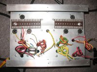
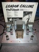
So far the chassis is done and transformers built and in place. That, I think is the easy part !!
I have made the chassis very compact, after-all it is a BABY Huey.
I've no doubt i will be asking for more advice at some point so I thought it only decent to show off my work so far !
Thanks to all those who have tolerated my limited electronics knowledge until now....! Can't wait to hear her first words.....
Ian. East Sussex UK.
Hi all,
I thought I'd build a Baby Huey as my first power amp scratch project, I have heard such good things about this amp and it seems that there is plenty of advice, expertise and helpful people on this site.
So far the chassis is done and transformers built and in place. That, I think is the easy part !!
I have made the chassis very compact, after-all it is a BABY Huey.
I've no doubt i will be asking for more advice at some point so I thought it only decent to show off my work so far !
Thanks to all those who have tolerated my limited electronics knowledge until now....! Can't wait to hear her first words.....
Ian. East Sussex UK.
Attachments
Last edited:
Nice start...
Thx for the pics. I'll be watching your build. I'm very curious on how the build goes and what it sounds like. But I need to finish one project before starting another..... No hurry but keep it rolling....
Thx for the pics. I'll be watching your build. I'm very curious on how the build goes and what it sounds like. But I need to finish one project before starting another..... No hurry but keep it rolling....
Ian (Sharkey22),
Good start, that looks about the ideal size chassis, you would not want to try to build it into anything smaller. Some of my greatest frustrations have come from trying build "stuff" into too small an enclosure.
Cheers,
Ian
Good start, that looks about the ideal size chassis, you would not want to try to build it into anything smaller. Some of my greatest frustrations have come from trying build "stuff" into too small an enclosure.
Cheers,
Ian
Ian (Sharkey22),
Good start, that looks about the ideal size chassis, you would not want to try to build it into anything smaller. Some of my greatest frustrations have come from trying build "stuff" into too small an enclosure.
Cheers,
Ian
Hello and thanks for your comments & encouragement. I am building this with pretty much zero tech knowledge following your schematic except for the HV B+ supply. I have a choke from an old Vortexion EL34 push-pull PA amp. I want to keep the PS as simple as possible whilst taking advantage of the choke. The HV on my transformer is 290-0-290 and the resistance of the choke is 125 Ohms. I am not sure of the chokes inductance so am slightly stumped so-far as component values go. I have had a few goes using PSUDII but am slightly confused regarding splitting the power for each channel also I think I may have been aiming for excessively smooth voltage at the expense of current/voltage stability under load...Please could you suggest a suitable and simple "ball-park" schematic for me to follow. I am reluctant to place my components order until I am confident with the PS design.
Regards Ian.
Ian,
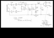
Here is a power supply, a bit over the top maybe but adjust to your taste.
Fuses are not absolutely required if you fuse the transformer primary.
The 10nF Class X and 2 x 10R before the rectifier diodes are intended to block any diode switching noise from coupling back through the transformer into other windings (particularly bias supply windings etc.). "Class X" is a safety rating and signifies a capacitor which is suitable for connecting from active to neutral on a mains supply. They will generally be a metalised polypropylene or metalised polyester.
Diodes are anything ultrafast and soft recovery, like UF4007
Diodes have supression caps fitted across them (optional), again to help suppress diode switching noise. Thezse should be 10nF 2kV high voltage ceramics.
C4 can be adjusted to trim the power supply voltage, 10uF will give a little less output voltage, 5uF and lower will give a lot less voltage. This cap has about 250 mA RMS ripple current in it (according to PSUDII). Check the rating of the cap you use (if in doubt use [for example] 2 off 10uF in parallel to give you the 20uF)
The 220K 2W before the choke is a bleed resistor to discharge the capacitors when you turn the power off. Since we are bleeding away current anyway then you might as well put a LED in series with the bleed resistor. Use a front panel mounted Green LED (or BLUE if that rtocks your boat) as a power ON indicator OR use a RED LED under the chassis as a warning that high voltage is ON.
Use a common 100uF/450V after the choke and then use 10R 2W "isolating" resistors in the feed to each channel.
At each channel use a 100uF/450V with a parallel 100nF/630V polypropylene cap connected with their +ve right at the output tranny centre tap feed and their neagtives at the point where the output tube cathode circuits return to 0V.
Cheers,
Ian
Attachments
Last edited:
Hello
I dont want to be a sceptic but I wonder what the purpouse is with all this filtering in a common mode noice cancelling PP configuration? Refered to famous constructions like QII for exemple a simple and small C-R-C for the powertubes is more then enough and gets it completely silence.
The splitter is another thing where "expensive" stuff like chokes etc can do some proper work. In some configurations G2 on the powertubes needs good treatment also but filtering powertube anodes with big chokes etc, where most of the current runs, seems like a bit over the top for me.
What is your opinions?
Edit: I recalled that the original version did not have this filter so maybe I was kicking in open doors and have to wear the silly hat for a while hat but I also recall (I think!?!) that for example Morgan Jones uses chokes for power anode load filtering in his Bevois Valley. IE I was more interested in the subject then critisizing anyone. I have the feeling that big chokes here can cause more pain then good, causing ringings between OPT and choke inductances etc.
Staffan
Last edited:
Staffan,
I did say that the supply was "a bit over the top maybe". Sharkey22 wanted to use the choke so I included it. Having built many amps I find that you may as well put this level of detail in from the start as it is usually messy to try and "shoe horn" extra components in afterwards.
The Baby Huey effectively has only a single power supply rail and so making it as clean as possible is unlikely to be wasted effort, some builders have even used regulated supplies.
Power Supply noise residuals are a source which form intermodulation distortion products with the signal (put a sine wave through the amp, look on a spectrum analyser and see all of the sidebands due to intermodulation with power supply ripple). If the ripple is'nt there or is greatly reduced (or if its harmonic content is greatly reduced) then so will those intermodulation products be reduced.
For Power Supplies I'd rather over design than under design.
Cheers,
Ian
I'm like you Ian. I tend to try and stay on the safe side on PSU filtering rather then the opposite.
On the topic of power anodes in PP config me and a friend did a test not so long a go. The build was a design by David Hafler borrowed from a Dynaco commercial paper http://www.the-planet.org/dynaco/Misc/Transformers.pdf (figure 3). The splitter is a floating paraphrase and GNF is different but on the output side it is close to Baby Huey (EL84 PP UL).
Sitting close to 100+ dB speakers we evaluated different B+ filtering to to the EL84s. We started with Haflers 40-100-40 C-R C but we had a clear hum. We also tried with different chokes instead of the R. The hum slightly reduced but so did the "happyness" in the music. It became duller.
We ended up on 40-100-140. It was completely silent with the ear in the cone and the happyness in the music was still there. Good tubematching and a balanced splitter is necessary for that.
So in filtering for PP anodes nowadays I rather tend to discover what is the absolute minimum for complete silence rather then going for the safe full blown filter.
Slightly OT but we also discovered a big difference on different capacitors here. Our final choice was good quality electrolytes on both C. We tested against big PIOs and polyprop and also cheap electrolytes. The favourite was Evox/Rifa PEG124 33 uF 450 V, 1 on first C and 3 on second added with a 40 uF motorrun on second C. With the ear in the cone in full volume and no signal we heared nothing but the slight breeze from the tubes (i dont know the english expression). Like slow landwash waves a summer night by the ocean.
Just my 2 cents. I dont have any claims for being right in all cases. It was a fun long night with the soldering iron and it gave many surprices.
cheers
Staffan
BH PSU
Ian , Thanks very much for that, just what I wanted, and thanks for the explanations for the various components. invaluable for a complete novice......I'll keep everything as you suggest and give it a go.
Bit busy with other stuff at the moment. I'll let you know how it goes in due course.
Ian.
Ian,
Here is a power supply, a bit over the top maybe but adjust to your taste.
Ian , Thanks very much for that, just what I wanted, and thanks for the explanations for the various components. invaluable for a complete novice......I'll keep everything as you suggest and give it a go.
Bit busy with other stuff at the moment. I'll let you know how it goes in due course.
Ian.
Last edited:
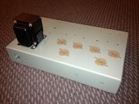
Just a quick report on progress....
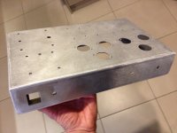
I've designed the chassis in solid works and had it laser cut then folded and welded at a local shop. I've just got it back from the paint shop this afternoon and fitted a few parts to see what it's going to look like....
I've never tried to attach files before so I hope they show!
I've designed the chassis in solid works and had it laser cut then folded and welded at a local shop. I've just got it back from the paint shop this afternoon and fitted a few parts to see what it's going to look like....
I've never tried to attach files before so I hope they show!
Attachments
That looks super Drewaudio! Are you going for an octal version or am I a bad counter?
best
Staffan
best
Staffan
Thanks! The plan is to build the octal version as I've got a box full of 6v6s but I've also got a few 6f6's in the st shape that I'd like to use.
The first problem is that I was told to allow 80 to 100 microns for the paint thickness inside all the holes. The reality is that the paint thickness is mo like 200 microns inside the holes which makes a planned 5.2mm dia hole into a 4.8mm dia hole🙁
The first problem is that I was told to allow 80 to 100 microns for the paint thickness inside all the holes. The reality is that the paint thickness is mo like 200 microns inside the holes which makes a planned 5.2mm dia hole into a 4.8mm dia hole🙁
Drewaudio, to accomodate for the folds, did you have to add length to each side to allow it to be bent?
Hi Gokite,
The particular version of solid works was from the local metal shop and calibrated for their folding machine and press. All I did was draw the chassis with the finished dimensions (eg external height, length, width) and hole shape/locations based on a sheet of 2mm aluminium and the software 'allowed' for the bends etc.
I've attached a 3D pdf output from the software that you can spin around. You will see that I've also set the bottom cover in by 2mm too.
The solid works file was then sent to a laser cutter before coming back to the shop to be bent in the press and then hand welded.
The cost will be about $160USD for the box which is not too bad considering that freight to New Zealand is a killer for any imported chassis. At least I get exactly what I want in terms of size, shape etc and I get a chassis with a decent wall thickness and all the holes pre-cut. 😎
Attachments
Hi everyone!
I am new to this forum. I found this while searching for a simple tube amp. This project seems great for a starter like me.
I do have some notions in electricity and electronics but I've never worked with tubes before. I am looking for some guidance too. I have a few questions regarding the building of this amp:
-What kind/brand of transformers work good with tubes? I am looking for some simple ones, I need them to be shipped to Europe (Spain) too. Anyone can help?
-Lurking around the thread I have realized that, eventhought you all are building the same amp, some people use fewer tubes. If I understand the diagram right, you need 4 tubes to build a mono amp right? That would make 8 tubes for stereo...is that right or am I missing something?
-Is it completely necessary to mount the tubes on the ceramic holders? I don't know where to get those from.
I'm hoping for your answer,
JUracan
Hi JUracan,
You would need 3 tubes per channel (2x EL84 and 1x ECC803). Some might use only one half of the double-triode ECC803 but two each (for some layout reasons or something else) - that's why you counted 4 per channel?
I only used Hammonds 1608 so far in mine and are quite pleased. The amp works already great with simple output transformers.
I will eventually upgrade the transformers with something better but at the moment the amp is my main system and I cannot afford to take it apart.
I bought the Hammonds while I was still living in NYC but I am sure you can buy them in Europe, too.
There are several forum members from Spain here, so I am confident they will give you good advice where to get decent transformers more locally and maybe even the ceramic tube sockets.
In Europe there are several good choices of transformers vendors; I get mine from Gerd Reinhöfer (Reinhoefer Electronic) recently, and the quality and performance is outstanding for that price.
Cheers,
Martin
Hi JUracan,
Welcome to the forum.
If I had to build this amp again from scratch I would pick up an old push pull amp that used EL84s ( 6BQ5s) as output tubes. You will get most of the parts that you need such as mains transformer, sockets, valves etc. You might get a pair of ECC83s (12ax7) that can be used instead of the ECC803S.
Another possible donor amp would be one that uses four ECL86's. Ian has posted a Baby Huey schematic earlier on in the thread that suits the ECL86.
Output transformers might still be a problem as this design requires the output transformers to have ultra linear taps.
If the question is " are sockets required " then for a new builder the answer is yes. Ceramic sockets I think are a matter of taste. A lot depends on quality. I bought new ceramic sockets for my first build but was very disappointed. I replaced them with much better teflon sockets pulled from ex military equipment.
HTH Bill
Welcome to the forum.
If I had to build this amp again from scratch I would pick up an old push pull amp that used EL84s ( 6BQ5s) as output tubes. You will get most of the parts that you need such as mains transformer, sockets, valves etc. You might get a pair of ECC83s (12ax7) that can be used instead of the ECC803S.
Another possible donor amp would be one that uses four ECL86's. Ian has posted a Baby Huey schematic earlier on in the thread that suits the ECL86.
Output transformers might still be a problem as this design requires the output transformers to have ultra linear taps.
-Is it completely necessary to mount the tubes on the ceramic holders? I don't know where to get those from.
If the question is " are sockets required " then for a new builder the answer is yes. Ceramic sockets I think are a matter of taste. A lot depends on quality. I bought new ceramic sockets for my first build but was very disappointed. I replaced them with much better teflon sockets pulled from ex military equipment.
HTH Bill
Last edited:
Thanks bayermar!
I'm not even sure about what kind of transformers I actually need. Are they normal trafos? I just need one with that output and that's it?
I had that same question, so you are telling me that ECC83s are compatible with ECC803S? Will I notice any difference in the sound? I have seen ECC83s pretty cheap, but the 803 cost quite a lot (compared to the other).
Where do you guys buy all this old amp stuff? Ebay? I take a look there from time to time, but most of them won't ship to Spain...
Why were you dissapointed with ceramic sockets? The first ones you got were bad quality/bad finishing on them?
I have other questions too, do I need to build it in a metal chasis or can I build it anywhere? I don't know if the chasis acts as a Faraday cage or it's just for looks.
Are all 9-pin sockets the same or do they have differences from tube to tube?
What would happen if you hook a electric guitar to this amp? Would it sound right or is it too linear? I'm not to much of a fan of distortion in guitars, will iI mainly want it to play music, but I might want to try connect my guitar.
What kind of output should I use? How many efficiency dB is just right?
I have another tonn of question regarding the best components to use (resistor/capacitor/etc wise).
Sorry if I am too n00b, I just got here.
Thanks for all the replies!
I'm not even sure about what kind of transformers I actually need. Are they normal trafos? I just need one with that output and that's it?
Hi JUracan,
Welcome to the forum.
If I had to build this amp again from scratch I would pick up an old push pull amp that used EL84s ( 6BQ5s) as output tubes. You will get most of the parts that you need such as mains transformer, sockets, valves etc. You might get a pair of ECC83s (12ax7) that can be used instead of the ECC803S.
Another possible donor amp would be one that uses four ECL86's. Ian has posted a Baby Huey schematic earlier on in the thread that suits the ECL86.
Output transformers might still be a problem as this design requires the output transformers to have ultra linear taps.
If the question is " are sockets required " then for a new builder the answer is yes. Ceramic sockets I think are a matter of taste. A lot depends on quality. I bought new ceramic sockets for my first build but was very disappointed. I replaced them with much better teflon sockets pulled from ex military equipment.
HTH Bill
I had that same question, so you are telling me that ECC83s are compatible with ECC803S? Will I notice any difference in the sound? I have seen ECC83s pretty cheap, but the 803 cost quite a lot (compared to the other).
Where do you guys buy all this old amp stuff? Ebay? I take a look there from time to time, but most of them won't ship to Spain...
Why were you dissapointed with ceramic sockets? The first ones you got were bad quality/bad finishing on them?
I have other questions too, do I need to build it in a metal chasis or can I build it anywhere? I don't know if the chasis acts as a Faraday cage or it's just for looks.
Are all 9-pin sockets the same or do they have differences from tube to tube?
What would happen if you hook a electric guitar to this amp? Would it sound right or is it too linear? I'm not to much of a fan of distortion in guitars, will iI mainly want it to play music, but I might want to try connect my guitar.
What kind of output should I use? How many efficiency dB is just right?
I have another tonn of question regarding the best components to use (resistor/capacitor/etc wise).
Sorry if I am too n00b, I just got here.
Thanks for all the replies!
- Home
- Amplifiers
- Tubes / Valves
- EL84 Amp - Baby Huey