For a power transformer, would this work: https://www.hammfg.com/part/369kx ? It has a 450 winding; a 6.3 winding and a 5 winding. All center tapped. In addition it has a 50 V tap on the top part of the 450 winding. I could use the top half of the 450 to get 225 volts - would that be enough? If so, how do I safely secure the lead on the bottom half of that winding? I don't like the idea of a high voltage lead just hanging there. I could use the 50 V tap for the bias and I could use the center tap of the 6.3 winding to elevate the heater voltage, using a voltage divider. Does anyone know a good spot on the BH pcb (I have Rev. 1.6) to tap into the B+ for elevating the heater? Also does anyone know a good spot to connect the pcb ground to chassis ground?
Thanks
Thanks
@jazzzman,
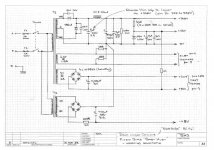
The Hammond 369kx should work fine, but you should use full-wave rectification and use both sides of the HV secondary. This will be done before you are connecting to the PCBs, with the CT connected to PCB ground at “Bias-2”. The 50 vac should work fine then for the bias supply and the junction of R40 and C11 (with +65 Vdc) could serve as a heater elevation source, as Ian (Gingertube) had done in his original “fixed bias” design, where he rectified 5 Vac for his 12AX7 heater. His PS is attached (got it from earlier part of this thread). I’m not aware of anyone that found such heater elevation necessary, though.
However, the 369KX is a relatively expensive transformer. You could also consider an Antek transformer with suitable 230Vac secondaries. You will need a small transf. for bias (again). https://www.antekinc.com/as-2t230-200va-230v-tube-transformer/
Attachments
Thank you, Francois, that is very helpful. Do you have any thoughts on where I should tap into the pcb ground plane for a connection to chassis ground?
I’m not sure I understand your question about “where I should tap into the PCB groundplane” correctly. IIRC (I’m traveling and can’t check my PCB) there are three terminals along the bottom of the PCB for Feedback, Input and Bias, each with a ground connector tapping into the PCB ground plane. I don’t recall reading about any issues related to using any specific connector for grounding the PCB, or needing a “ground lift”, but purist will advise you to connect the chassis only to the Input ground, possibly with a “ground lift” between the PCB circuit and the chassis. See figure 15.16 in the Valve Wizard’s chapter on grounding.
http://www.valvewizard.co.uk/Grounding.pdf
http://www.valvewizard.co.uk/Grounding.pdf

Thank you, Francois, my question was poorly worded. On my solid state builds I have one wire from the psu pcb attach to the safety earth bolt through a thermistor. I was wondering if you do something similar with a tube build.
On the EL84 Baby Huey PCB (R1.6 that you have) the “power supply PCB” is included, so no worries there. I don’t know of anyone that needed a ground lift (such as depicted in Valvewizerds fig 15.16). If you experience hum/ground loop issues in your build you could easily retrofit it.
Last edited:
Hi @jazzzman ,
if I were you I would contact https://www.triadmagnetics.com/ or similar suppliers in USA asking for specific details.
No need to buy multiple transformers and pay multiple shippings.
if I were you I would contact https://www.triadmagnetics.com/ or similar suppliers in USA asking for specific details.
No need to buy multiple transformers and pay multiple shippings.
You are welcome!
I don't have the transformers with me, but IIRC I ordered (one trafo for two channels):
0-260V 400mA (to land around 340V B+)
3.15-0-3.15V 4A (for heaters, central tap for a 470k-100k||10u elevator from main B+)
0-60V 100mA (for bias and PowerDrive, adjust resistors accordingly)
For others: just consider I have transformers with 8k Raa and 23%UL and other adjustements.
Zintolo,
Did you order this transformer from https://www.triadmagnetics.com ? I did not know they have such transformers. Could you point to it in their catalog, please.
Did you order this transformer from https://www.triadmagnetics.com ? I did not know they have such transformers. Could you point to it in their catalog, please.
Hi Francois,
I ordered my trafos in EU, but a rapid search on Google showed that producer that says he does custom trafos.
I ordered my trafos in EU, but a rapid search on Google showed that producer that says he does custom trafos.
By ”that producer” do you mean triadmagnetics? I will be delighted if they will make tube power transformers on custom order, but I had assumed they deal in quantities of 100s. I will be glad to be wrong on this one.
I absolutely don't know them, but at least here in Italy you can find someone that can produce custom transformer every 100 km.
I just linked the first one that google proposed in USA just to suggest to try to contact someone locally to custom build the power transformer.
I just linked the first one that google proposed in USA just to suggest to try to contact someone locally to custom build the power transformer.
- Home
- Amplifiers
- Tubes / Valves
- EL84 Amp - Baby Huey