Looks great.
A 12AU7 will work but will have MUCH worse distortion performance in that position. Third harmonic is reinforced in a push-pull stage and the 12AU7 has about ten times higher third than a 6SN7...
A 12AU7 will work but will have MUCH worse distortion performance in that position. Third harmonic is reinforced in a push-pull stage and the 12AU7 has about ten times higher third than a 6SN7...
L'esprit d'escalier: lose the 500K input pot. Assuming you have a preamp, just use a fixed resistor between 100K and 1M (value not critical). Reason is the Miller capacitance of the 12AX7 stage- at lower volume control settings, the high end will be severely compromised. For a 100pF Miller capacitance and a 500K source, the f3 is slightly higher than 3kHz. If the control is always operated near full on, this is less of an issue, but why have redundant volume controls if you don't need them?
ouch! might as well keep the 12au7s in storage. 😀
also found this morning some 6201, and 5751 in my tube basket. already I am having a tube lineup for tube rolling.
i've ordered a separate tranny which has a 3.15-0-3.15 @2A (for 6sn7 and 12ax7 heaters) and 100V @50mA (for bias supply). I was going for a 50V winding (same as extra winding in EICO orig tranny) but I figured it would be best to have more voltage when I need less than have less voltage when I need more. 😀
Like you advised, I'll just setup a divider network with a pot in the middle and fixed resistors on top and bottom to obtain a suitable range for the bias adjustment.
I'm glad you approved of the schematic, I start collecting parts for this project. 😎
SY said:L'esprit d'escalier: lose the 500K input pot. Assuming you have a preamp, just use a fixed resistor between 100K and 1M (value not critical). Reason is the Miller capacitance of the 12AX7 stage- at lower volume control settings, the high end will be severely compromised. For a 100pF Miller capacitance and a 500K source, the f3 is slightly higher than 3kHz. If the control is always operated near full on, this is less of an issue, but why have redundant volume controls if you don't need them?
deciding to pot or not to pot can be hard since I usually use my cdp direct to my amp, but if the pot will ruin the sound then I won't think twice. could there be any other work around on this?
If you're driving from a solid state CD player, you don't need a super high input impedance. Change to pot to 20k and all will be well.
SY said:...my personal preference runs to 6SL7->6SN7. But there are a lot of other fine possibilities.... But a 12AT7 will also perform great in the first hole while showing a lower input capacitance.
i hear the 12AT7 (ECC81)and 12AX7 (ECC83) are a bit strident.
JojoD818 said:
Any alternates for the 7025 with this ckt? ECC83? ECC88 (limited gain)? or octal 6SL7?
hi navin,
the original used a 12ax7 though I think a 6SL7 would do a great job but an ECC83 can also be used. I will use the 7025 since I already have it.
the original used a 12ax7 though I think a 6SL7 would do a great job but an ECC83 can also be used. I will use the 7025 since I already have it.
JojoD818 said:hi navin,
the original used a 12ax7 though I think a 6SL7 would do a great job but an ECC83 can also be used. I will use the 7025 since I already have it.
6SL7 I think might be my best option.
navin,
so will you build it too? it would be cool to have someone work on the same amp (almost 😀 ) from somewhere else on the globe. 😎
🙂
so will you build it too? it would be cool to have someone work on the same amp (almost 😀 ) from somewhere else on the globe. 😎
🙂
JojoD818 said:navin,
so will you build it too? it would be cool to have someone work on the same amp (almost 😀 ) from somewhere else on the globe. 😎
🙂
I intend to build something similar.
So far I am just collecting parts.
what i got so far...
8 Svetlana EL 34
4 6SN7
2 ECC 88
what i need
4 6SL7
a tested ckt for triode and UL mode.
I dont have any design skills.
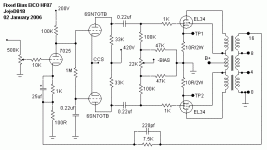
navin said:I am thinking of using this schematic but replacing the 7025 with a 6SL7 as the 7025 is not available in India what other changes would i need to make?
you can use a 12ax7 in place of the 7025 and change nothing. I think a 6sl7 will also work in that manner. Unless some of our friends here have other advice. 🙂
navin,
what I did in my tube amp was to use a high quality switch in the screen for ultralinear/triode operation.
JojoD
what I did in my tube amp was to use a high quality switch in the screen for ultralinear/triode operation.
JojoD
JojoD818 said:navin,
what I did in my tube amp was to use a high quality switch in the screen for ultralinear/triode operation.
JojoD
hey where is this switch. i cant find one of the ckt posted earlier.
BTW what is TP1 and TP2 for? Where do they go?
hi navin,
TP1 and TP2 are test points, I will use this to measure the cathode voltage (or the voltage drop across 10 ohms resistors) to calculate the plate (plus screen) current per tube.
the triode/ultralinear switch is not in the schematic, i implemented that in my other amp. it is fairly simple because the switch is just toggling the screen through the ul tap of the opt tranny for ultralinear operation or to the plate of the opt tube for triode operation.
JojoD
JojoD818 said:the triode/ultralinear switch is not in the schematic, i implemented that in my other amp. it is fairly simple because the switch is just toggling the screen through the ul tap of the opt tranny for ultralinear operation or to the plate of the opt tube for triode operation.
the ckt we have is configured for UL right? (as the screen is connected to the UL tap) then to configure it for triode all one has to do is connect the screen of the EL34 to the plate? shouldn't there be a resistor between the screen and the plate?
BTW the 7025 is a dual triode right? so you need only 1 per stereo amp? right? if so maybe your ckt should read as 1/2 7025?
BTW what is the primary of the OPT 6.6k or 5K?
navin,
yes you got it right. also there should be a resistor there but I tried it without one. i've seen amps use 100 ohms in there.
yes the ckt uses one triode (per channel) of a dual triode 7025/12AX7/ECC83. and yes again, for clarification purposes, it should read/labeled 1/2 7025.
yes you got it right. also there should be a resistor there but I tried it without one. i've seen amps use 100 ohms in there.
yes the ckt uses one triode (per channel) of a dual triode 7025/12AX7/ECC83. and yes again, for clarification purposes, it should read/labeled 1/2 7025.
JojoD818 said:yes you got it right. also there should be a resistor there but I tried it without one. i've seen amps use 100 ohms in there.
yes the ckt uses one triode (per channel) of a dual triode 7025/12AX7/ECC83. and yes again, for clarification purposes, it should read/labeled 1/2 7025.
100 ohms? isn't that low. I would have guess 1-1.5-2.2K.
I guess one can use a ECC88 (lower gain) or 6SL7 or any dual triode then?
- Status
- Not open for further replies.
- Home
- Amplifiers
- Tubes / Valves
- EL34 schematic confusion