General build question here.
I'm in the process of assembling my amps, initially I was going to omit the feedback connections but am now questioning that's a wise decision?
So I have a couple of questions.
1 - Any issue adding a single pole switch to the chassis so that I can switch the positive supply to the feedback system?
2 - Should the feedback cable be shielded as its directly into the input stage?
Cheers
Hi TristanC
Would it be possible to do the heater wiring using the twisted wire concept and kept away from the board tracks. Board tracks may leak AC hum? and lean more towards a heater DC supply scheme?
The weight of copper might cause PCB pricing to skyrocket.
Thanks
Earl Josh
Would it be possible to do the heater wiring using the twisted wire concept and kept away from the board tracks. Board tracks may leak AC hum? and lean more towards a heater DC supply scheme?
The weight of copper might cause PCB pricing to skyrocket.
Thanks
Earl Josh
Thanks Ian. Noted. I'm tempted to use (shock, horror) a couple of turrets as the footprint for this component to allow "select on test" without lifted pads / easier soldering etc. That or a bit of free-style point-to-point from resistor-lead-clippings-as-temporary-turrets.
My transformers have arrived from Primary Windings and Toroidy, so just layout and a PCBway order to go. Heater current requirements may require a 2oz copper order and wide traces for certain areas.
Tristan
Hi Earl,
- I see the simplification in doing the 'up and over' route with external wiring. But it makes it a less-neat solution. I've a single feed point from the transformer, the artificial center tap and then off to the heaters - it's this area that requires the fattest traces to deal with the current, before it splits off to each channel.
- As I understand it (hoping someone will correct me) twisting wires keeps the two EM fields as parallel as possible to cancel out as much as possible. What could be more parallel than two straight traces on a PCB, either top and bottom or side by side (or both).
- Twisted pairs can be simulated with PCB traces and vias, but I think that's a bit overkill and the current capacity of the vias would need to be checked.
- I plan to keep the heater runs as direct and short as possible, with signal carrying components / traces crossing at 90 degs etc etc.
- I may also use a humdinger pot in place of the artificial centertap to further cancel any noise - but Pete's board doesn't do this and I can't hear / measure much hum.
- and as it's push pull there's a certain amount of common noise cancellation.
But basically, yes, up and over is possible and may be the only option once I do the calcs for trace width / clearance for 7.2A @ 6.3V...
[EDIT] that would be ~2.34mm trace width and 0.62mm clearance for a 2inch long trace at 7.2A, 10C temp rise with 2Oz copper.
Tristan
I've had no issue using AC heaters with the DCPP so had planned to borrow Pete's routing method from his PCB. My thought process is something like:Would it be possible to do the heater wiring using the twisted wire concept and kept away from the board tracks. Board tracks may leak AC hum? and lean more towards a heater DC supply scheme?
- I see the simplification in doing the 'up and over' route with external wiring. But it makes it a less-neat solution. I've a single feed point from the transformer, the artificial center tap and then off to the heaters - it's this area that requires the fattest traces to deal with the current, before it splits off to each channel.
- As I understand it (hoping someone will correct me) twisting wires keeps the two EM fields as parallel as possible to cancel out as much as possible. What could be more parallel than two straight traces on a PCB, either top and bottom or side by side (or both).
- Twisted pairs can be simulated with PCB traces and vias, but I think that's a bit overkill and the current capacity of the vias would need to be checked.
- I plan to keep the heater runs as direct and short as possible, with signal carrying components / traces crossing at 90 degs etc etc.
- I may also use a humdinger pot in place of the artificial centertap to further cancel any noise - but Pete's board doesn't do this and I can't hear / measure much hum.
- and as it's push pull there's a certain amount of common noise cancellation.
But basically, yes, up and over is possible and may be the only option once I do the calcs for trace width / clearance for 7.2A @ 6.3V...
[EDIT] that would be ~2.34mm trace width and 0.62mm clearance for a 2inch long trace at 7.2A, 10C temp rise with 2Oz copper.
Yes, this'll come in to it. 1oz is $5/board, 2oz is $10/board for a 5 PCB order. So still not too bad...The weight of copper might cause PCB pricing to skyrocket.
Tristan
Last edited:
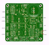
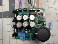
I am building the EL34/12AX7. Just finished building and powered up the PSU (Power Supply MK2, Rev2.0).
Line Voltage: ~119V
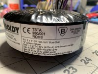
Transformer: TOROIDY TSTA 250/001
No load voltages are below in the picture. A few questions :
Line Voltage: ~119V
Transformer: TOROIDY TSTA 250/001
No load voltages are below in the picture. A few questions :
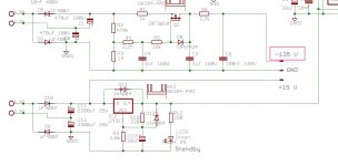
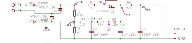
- The HV voltage seems a bit high at 486V.
- The -bias voltage is -93V , The schematic I have seems to indicate this should be -135V
- Do the overall voltages look good to connect to the Amp boards? Is there a better way to test the voltages.
- I hope the transformer hookup is fine.
Attachments
Last edited:
I am building the EL34/12AX7. Just finished building and powered up the PSU (Power Supply MK2, Rev2.0).
Line Voltage: ~119V
Transformer: TOROIDY TSTA 250/001
No load voltages are below in the picture. A few questions :
- The HV voltage seems a bit high at 486V.
- The -bias voltage is -93V , The schematic I have seems to indicate this should be -135V
- Do the overall voltages look good to connect to the Amp boards? Is there a better way to test the voltages.
- I hope the transformer hookup is fine.
Use the Pink-Brown wires from the transformer instead of the Pink-Orange.
gabo
Hi Gabbar
• Try changing the orange (330v AC) lead to the brown (275v AC), that should bring your HT down to within range. Remember to cover/isolate the orange lead for safety
• -93 seems low, think I'm getting 110v DC
• See attached , also in the tread a member posted a schematic with voltages on the amp under test. Will find tonight and repost.
• Yes all correct
Attachments
Dagwood/gbowling,
Thanks for all the help!
Did that and I am seeing 408V. Think that's in the safe zone. Whats the max the setup can handle ? Will I loose some power due to the lower voltage.Try changing the orange (330v AC) lead to the brown (275v AC), that should bring your HT down to within range. Remember to cover/isolate the orange lead for safety
This is still an issue. Added a picture with voltages measured at all junctions. Maybe that will give a clue. Resistors seems to be all placed correctly.-93 seems low, think I'm getting 110v DC
No luck form my side as well.Also in the thread a member posted a schematic with voltages on the amp under test.
Thanks for all the help!
Attachments
Can you try to change R2 to 220K?
Also -143V input is kind of too low for -135V output. It needs to keep difference big enough to make sure it works all the time.
Supply Filtering and why Capacitance Multipliers are NOT the Answer
Also -143V input is kind of too low for -135V output. It needs to keep difference big enough to make sure it works all the time.
Supply Filtering and why Capacitance Multipliers are NOT the Answer
Last edited:
Hi Gabbar
That will depend on the voltage the caps 3 and 10 used, spec is 500v, so allow 10% for safety, max would be around 450v on the B+
Did that and I am seeing 408V. Think that's in the safe zone. Whats the max the setup can handle ? Will I loose some power due to the lower voltage.
That will depend on the voltage the caps 3 and 10 used, spec is 500v, so allow 10% for safety, max would be around 450v on the B+
Ran out of time last night but will find the file and upload later today.No luck form my side as well.
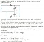
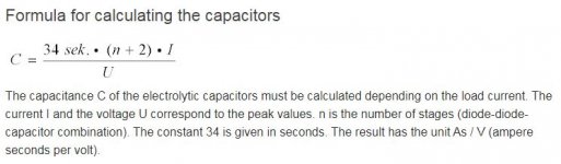
a voltage doubler cannot do magic either, as "doubler" already says, that should be clear to everyone. In addition, you should only measure under load and not while idling, see also
https://www.diyaudio.com/forums/tubes-valves/326920-el34-baby-huey-amplifier-74.html#post6148632
here, by the way, r2 was reduced to 22k!
https://www.diyaudio.com/forums/tubes-valves/326920-el34-baby-huey-amplifier-74.html#post6148632
here, by the way, r2 was reduced to 22k!
Attachments
Last edited:
Gabbar,
gingertube recommended trying 22k value for R2. I believe most folks used that value. See post #718, 738 and around there.
gingertube recommended trying 22k value for R2. I believe most folks used that value. See post #718, 738 and around there.
Last edited:
Can you try to change R2 to 220K?
I did not remove R2 but put another resistor in parallel to the 470K I have. I am seeing the below boosted voltages:
470K in parallel : 112.4V
330K in parallel : 116.6V
100K in parallel : 128.6V
I think I am going to replace the R2 with something like a 68K to cross the 135V threshold. I don't have any 0.6W in stock, not sure a .25W will be fine here.
Are there any ill effects of a lower R2 value ?
-Gab
Hi Gabbar,
What value did you use? I did the same as these PCB's are very hard to remove parts once in place, I used 23.2k in parallel with the 470k, works out to near enough 22k.
You are welcome, I found them very helpful and am grateful for all Marc's work on this project until his passing.
Have you read through the entire thread? if not I suggest you do 🙂
What value did you use? I did the same as these PCB's are very hard to remove parts once in place, I used 23.2k in parallel with the 470k, works out to near enough 22k.
You are welcome, I found them very helpful and am grateful for all Marc's work on this project until his passing.
This relates to the IRF9610 pinout error on the 2019 PSU PBC.You need to read post #738 where Ian (gingertube) explains this mod, it's very easy to complete and a must do.gingertube did recommend 22k for R2 , but had much different R1 and R6 values as well, both 100R. Re-positioned the Zener etc., that will need some track surgery.
Have you read through the entire thread? if not I suggest you do 🙂
Just remember that those value are just guidelines and AFAIK nobody yet shared a full BOM for every kind of tube and class the amp is working on.
General guidelines are that for the drivers you need three times the bias voltage on the negative side, and on the positive side at least 25V more than the maximum voltage you want to have on g1 of the power tube. So If you stay in class A1 or AB1 it is ok to have let's say +30V, in you want to go into A2 or AB2 you need to raise it.
When voltages increase, just consider Q1, Q7 and Q9 maximum allowed voltages across them, and the possibility to upgrade those BJTs to higher Vce ones.
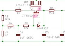
I got the PCB from the recent Group Buy organized by Algar_emi . This version seems to have the pin out issue fixed. Zener D8 is between the Gate and Source of IRF9610. I matched the actual board layout to the schematic below. I think previously I was referring to a older version of the schematic. It's a bit confusing as there are multiple versions floating around with subtle changes and creation Date/TS not being updated.This relates to the IRF9610 pinout error on the 2019 PSU PBC.You need to read post #738 where Ian (gingertube) explains this mod, it's very easy to complete and a must do.
Making some progress on that.Have you read through the entire thread? if not I suggest you do
I am just going for the most common version with EL34/12AX7. Never went near a tube amp before this 🙂 Attaching the BOM that was shared in the Group buy.Just remember that those value are just guidelines and AFAIK nobody yet shared a full BOM for every kind of tube and class the amp is working on.
Attachments
@Francois G
gingertube did recommend 22k for R2 , but had much different R1 and R6 values as well, both 100R. Re-positioned the Zener etc., that will need some track surgery.
Hey Gab,
Probably a typo in the quote, but for the PSU values of R1 & R7 are now 1k, R6 is unchanged at 2k7.
The -135V bias was to accommodate “big tubes”, your build with EL34s should be fine with what you have now. On the other hand, maybe you want to try KT88s in the future, and then you do want closer to -135V.
Good luck.
Francois,
Are you running KT88’s? If so, would you be so kind as to shoot me over the BOM and any related documents you have for it? That is the tube choice I would like to go with and am in the process of getting everything together on Digikey and Mouser for a purchase.
I am also purchasing the parts I need for my Pearl 2 boards, power supplies for this build and the Pearl along with parts for the 3 guitar amps I need to build. I am trying to keep my orders down to save on shipping charges so the more I can order in the first order would be the best idea.
What I am planning is to use “Wayne’s BA 2018 linestage”, Wayne’s Pass Pearl 2, Bill Thompson’s motor controller for my Rega Planar 3 with the BH as the amp.
My understanding is the KT88’s are the tubes that will give me the highest wattage and that is what I am looking for.
Thanks, James
Hey Gab,
Probably a typo in the quote, but for the PSU values of R1 & R7 are now 1k, R6 is unchanged at 2k7.
For those who want to look into the values of PSU R1, R2 & R6 and the effect they have on Vout and current through the Mosfet - gbowlings post #776. He thought R6 should be below ~1k5.
Last edited:
- Home
- Amplifiers
- Tubes / Valves
- EL34 Baby Huey Amplifier