My next is not based on fact or research, just my thoughts.AKSA said:but my argument stands, and is confirmed subjectively over many years. A shunt cap acting on a signal has less sonic influence than one in series with the entire signal.
If a cap is used to roll off the response (as in parallel with the upper leg feedback resistor) then it removes/feedsback signal above the audio range.
If it is not perfect the error in the signal will be many times lower than the main signal, so is less likely to be audible. Since the signal error is also way above the audio range that too makes it less audible, provided the error from the perfect capacitor does not cause the amp be change it's stability margins.
It seems that the tiny caps 2p2F to 22pF // 20k will have two mechanisms that when combined make them near enough inaudible. Even if the Ru~100k the same inaudibility argument applies.
However, if the cap passes audio signal back to the NFB node then the opposite applies. It becomes very audible if there is an error from perfect capacitance.
I think the above two contrasting arguments support Aksa's contention.
Now let's apply a similar argument to the RF cap at the input.
It too passes above audio to ground. If it were less than perfect the effect should only apply at the higher than audio frequencies and at a very low level since most is already rolled off.
Why in this situation does it appear that adopting different types of caps sound different (mica, polystyrene, polypropylene, NP0 ceramic).
Or is my analysis spurious?
Thanks Andrew......
Here's another instance.
A HP filter on a passive crossover contains a series cap to the tweeter. This cap is very, very significant to sonics.
A LP filter on a passive crossover contains a shunt cap to ground for the woofer. This cap is nothing like as touchy, and can be a good quality bipolar electro. Try a bipolar electro in the tweeter circuit, and you quickly notice that it's much worse sounding than a film cap.
This is not the same situation, and the argument is by analogy, but at least similar sized caps are involved in a passive crossover.
Cheers,
Hugh
Hi,
I think Aksa is agreeing with my analysis.
Let's just take it one step further and this agrees with what Aksa said in his most recent post.
If the cap is "working" in the audio frequency range then near perfection is required in the capacitance parameters.
If the cap is "working" outside the audio frequency range then it has much less effect on the audio range and some error in capacitance can be tolerated.
Is anyone willing to explain why the RF filter does not fit with this model?
Hi Andrew,
If a capacitor does have significant voltage across it and it misbehaves, then it will have a large effect on the sonics. That is why the small cheap ceramics make an amp sound so bad. They do have a large voltage across them and are normally in a high impedance node. So if they then react in a non-linear fashion that is outside their normal effective range, you will hear them.
CDom is a prime example of this.
-Chris
Maybe. 😉Is anyone willing to explain why the RF filter does not fit with this model?
If a capacitor does have significant voltage across it and it misbehaves, then it will have a large effect on the sonics. That is why the small cheap ceramics make an amp sound so bad. They do have a large voltage across them and are normally in a high impedance node. So if they then react in a non-linear fashion that is outside their normal effective range, you will hear them.
CDom is a prime example of this.
-Chris
Ok, so after many posts about caps, I will not use one, ever! Just kidding, but I think you get the point.
So to get a little closer to the topic, I have an issue with my circuit. At high levels, but below clipping I have audible distortion. It occurs at low frequencies only. My scope shows problems with very low frequency square waves which I will post. Even low frequency sinewaves clip in a strange manner.
The amp is only down ~1.6DB at 100Khz and 3hz. That is testing with a sinewave at 1W to 170W.
Here is the circuit below, with any changes I have made since last posting it.
Thanks, Don
Attachments

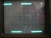
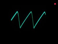
Here is the same input level trying to generate a 20hz square wave at 93V P2P into 8R0. It shows significant overshoot, (my best estimate is ~30%) causing clipping and an extreme tilt at the tops of the waveform. Even at (way) lower drive levels it still overshoots and tilts as demonstated by this scope shot, though without the clipping issue.
Were is the problem, and how can I fix it?
Help?
Thanks, Don
Were is the problem, and how can I fix it?
Help?
Thanks, Don
Attachments
Hi Don,
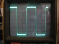
That's not overshoot.
Something is collapsing. Your signal level is not maintained for some reason.
Use your scope triggered on that waveform and poke around looking for something else that is also collapsing. Do not overlook your supplies. I know, I don't see a classic ripple on the tail end, but it's still worth a look. Also look at your grounds for signal that shouldn't be there.
-Chris
Don,
I too believe it could be power supply. The very low frequency is draining the supply caps, voltage is collapsing after a short time, and the 46.5V peak voltage of the square wave is dropping because current can't be sustained into the load.
Normally you will see differentiation of the signal (sag!) with a capacitive input at low frequencies. Since your gates a direct coupled, that is not the problem here.
Very little music goes below 40Hz; this is a tough test.
However, if this problem persists at lower voltage output, I'd be looking at first the current sink supplying the voltage amp, and then the Lender topology driving the voltage amp. In fact, for an easy diagnosis, try moving the source of the voltage amp via a suitable degeneration resistor to the rail. Choose this resistor to maintain LTP balance.
Hugh
I really appreciate the help. However I am a little lost here! I noticed the problem on music and followed up with testing. Why should the amp have such poor LF performance? It is direct coupled! If it were very low capacitance on the power supply or a small transformer I could see the problem! Maybe! You have not seen the power supply, or the fact that the electro caps are circa 1984. I will post that below.
There is severe square wave tilt at just 1W of output at 100hz. Maybe it’s the caps? The amp can do +110V P2P before clipping at 1Khz and above.
Maybe there is some math that can help determine the caps values/function. The circuit draws ~350ma at idle. What kind of ripple voltage should I be looking at with this supply at idle, given my circuit?
Attachments

Don,
This points to a topology or dimensioning issue. At 1W it cannot be the power supply!
Have a look at the voltage amp, then consider the current sink which supports it. Make sure the currents in the LTP are balanced at idle; this is very important. Compute the currents in each arm by measuring voltage across the tail resistors.
I doubt you need three series LEDs for voltage reference; two is usually quite sufficient with mosfets.
One further possibility; the direct coupling to the gate of the fb mosfet could be causing latchup at low frequencies. Try inserting a 470uF cap from the shunt fb resistor to ground.
Cheers,
Hugh
Hi Don,
Just for grins and giggles, would you please post a shot of your supply ripple? Please include the ranges corrected for your probe (the actual scale factor).
-Chris
Just for grins and giggles, would you please post a shot of your supply ripple? Please include the ranges corrected for your probe (the actual scale factor).
-Chris
Hey Don,
What a nuisance. Rather limits the selection of music you can play on this amp. 😉
When weird things happen at small signal levels it means one of two things: a component or wiring fault or a stability issue.
I'm sure you've checked the wiring and had a look at the psu lines and so on by now. I'd also check the ground connections to ensure they are all ok and starred. No need to insert a cap in the fb.
Let me know when you've done this. I have a bunch of methods to sort any stability problems out.
Brian
PS on your scope photo of the 20Hz squarewave, is the waveform offset or is is centred on zero volts?
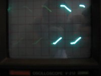
Chris here is a shot of the negative rail. The positive rail was inverted and equal voltage. The scope is at 5mV/division. P2P was 4 divisions, so 20mV P2P. The amp was at idle, which means it was drawing about 350mA from the supply.
I will bet there is some math to calculate the value of the filter caps from this information! I just don't know how to do it.
Thanks, Don
I will bet there is some math to calculate the value of the filter caps from this information! I just don't know how to do it.
Thanks, Don
Attachments
Hi Don,
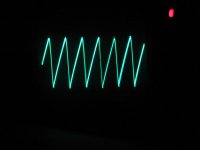
Could you please expand the time scale so we see 2 cycles maximum? I want to see the leading edge of the ripple.
-Chris
Could you please expand the time scale so we see 2 cycles maximum? I want to see the leading edge of the ripple.
-Chris
Hi Don,
Thank you!
See that elongated peak, or "pip" on the most negative portion of the waveform? That is what I look at to determine if the caps are okay or not. Yours look old, but fine otherwise.
-Chris
Thank you!
See that elongated peak, or "pip" on the most negative portion of the waveform? That is what I look at to determine if the caps are okay or not. Yours look old, but fine otherwise.
-Chris
I am still trying to figure out what is going on. How many LF zeros and or poles should this circuit have? I know that with 1W sinewaves the circuit doesn't start to rolloff until about 4hz. However the squarewaves start to tilt below ~100hz. Does that mean though there is little amplitude lost, we are seeing a large phase shift? Possibly from the additional passive power supply filtering on the FE? Maybe someone can give me an idea why a fully DC coupled circuit will have any rolloff at all!
Maybe I can use it as a super tweeter amp. 😀 😀 😀 220WRMS
Thanks, Don
Maybe I can use it as a super tweeter amp. 😀 😀 😀 220WRMS
Thanks, Don
- Status
- Not open for further replies.
- Home
- Amplifiers
- Solid State
- EF Output Stage