Don,
A dc coupled amp should produce perfect square waves at low frequencies. That's easy, or should be. According to the schematic you posted earlier there shouldn't be any LF roll-off.
Instability can show itself like this. It is pernicious like the Knids.
What suggests your circuit is unstable?
- you need C20 to keep it from oscillating outright
- your LTP comprises highly capacitive FETs: IRF610 are too big and slow for this circuit (like asking Arnold Schwartzeneggar to figure skate)
- connecting Q6 source to R2 dereferences C21.
Rememdies (in order of ease):
1) replace Q1 and Q2 with faster FETs (lower capacitance)
2) Change R36 to 220 ohms or more to reduce the forward gain
3) get rid of R9 and R11
4) connect Q6 source directly to the + rail (and re-adjust the dc offset)
5) make R2 1k or more
6) then get rid of C20
7) make C21 larger
Are you aware that this is a "high feedback" design? The LF OL gain is enormous. Is that what you wanted to make?
traderbam said:Don,
A dc coupled amp should produce perfect square waves at low frequencies. That's easy, or should be. According to the schematic you posted earlier there shouldn't be any LF roll-off.
Instability can show itself like this. It is pernicious like the Knids.
What suggests your circuit is unstable?
- you need C20 to keep it from oscillating outright
- your LTP comprises highly capacitive FETs: IRF610 are too big and slow for this circuit (like asking Arnold Schwartzeneggar to figure skate)
- connecting Q6 source to R2 dereferences C21.
Rememdies (in order of ease):
1) replace Q1 and Q2 with faster FETs (lower capacitance)
2) Change R36 to 220 ohms or more to reduce the forward gain
3) get rid of R9 and R11
4) connect Q6 source directly to the + rail (and re-adjust the dc offset)
5) make R2 1k or more
6) then get rid of C20
7) make C21 larger
Are you aware that this is a "high feedback" design? The LF OL gain is enormous. Is that what you wanted to make?
Traderbam, Let me preface my comments by saying that I know little regarding AC theory. I continue to read and learn much on this site. You may be right with everything you stated above, however I have read conflicting information regarding some of your statements above. Please help me learn, don't just tell me what I am doing is wrong.
If a linear, unregulated power supply has a finite resistance (not 0) it will reduce the gain of the circuit when loaded. Capacitors take time to charge and discharge, and can only hold a specific charge, (not infinite) so they will eventually have voltage/current sag at some point also. Conclusion on my part, you can have reduced gain through power supply drop. I believe it would show as a tilt of a squarewave, and a reduction of gain, which gets worse with lower frequency. (a DC signal will take the power supply to it's lowest potential, no time for the caps to charge) So is this not a pole?
Regarding the compensation, I was told by Nelson Pass to put a cap on "Q6 or/and Q4", being the middle of the road guy I am, well you know the answer! The amp only oscillated after a certain output bias level was reached, not all the time. We are also talking ~2.5Mhz oscillation frequency! I might have been able to achieve the same thing with just 1 cap on either Q4 or Q6 and get same effect, but we all know that Cdom compensation increases HF distortion when GFB is applied, reduced gain at HF I believe is the cause. So my thought was stability with half the Cdom by doing it my way! Probably no difference in real performance though! BTW no matter how high I bias the outputs I can't find any oscillation.
1) 610's as the LTP! Nelson Pass uses them in some circuits. Charles Hanson used 510's in one of his amps. So maybe Arnold can at least dance. (see True Lies!) How many other devices will hold up with over 9mA's running through them at these voltages.
Any source degeneration cancels a Cdom caps effectiveness??
2)R36 is Q11's base resistor. I am lost there!!!!!
3)R9 and R11 could probably be eliminated, however C1 will present a low value of resistance at high frequency. I just don't see any real benefit if I eliminate them, other than potential stability issues.
4) Noted well above.
5) Making R2 the same as R1 does not imply balance. Right now the LTP is balanced to within 0.0003mA
6)+7) Back to the old chestnut that you can't Cdom Q4, only Q6. All that I can tell you is that it works!
Regarding FB, I don't know what the OL gain is. Nelson Pass stated that he would not recommend running it at more than ~20DB of gain CL. I can state with certainty that until I reduced the gain to less than 26DB the DC offset was all over the place. This implies to me that I was not getting very much FB at these higher gain/ lower FB settings. If it had that much gain at DC, why would the offset be so bad at 30DB CL gain. (+-500mV drift)
To all, most especially Traderbam, sorry about the diatribe. I just don't see any signs of instability with any of the loads I have tried, and have played the amp into several speakers without other issues. I see no issues at 10, 100, 1000, 10,000, or 100,000hz with any signals that look like oscillation. I know that there are LF poles associated with the power supply, and I believe that where the problems lie.
Please prove me wrong or right, it doesn't matter. I just want to learn more, and finish my project!
I believe that in the spirit of the DIY Forum that people will teach me. If I want a lecture, I will talk to my boss.
Thanks, Don
Don,
I'm just offering ideas to help you get the thing working. Maybe more ideas than you care for. It is very hard to know what's wrong without more information: it's all guesswork. It could just be a faulty part or a bad connection.
I don't know what level of advice you want. So forget what I've suggested for now. If you want to ask me a specific question I'll try to answer it.
"If a linear, unregulated power supply has a finite resistance (not 0) it will reduce the gain of the circuit when loaded."
Why? The circuit gain should not be affected much by psu ripple (unless it is very big - how big is it?) because the gain is mainly set by the transistor currents and resistors. Your current sources should be fairly steady.
"Capacitors take time to charge and discharge, and can only hold a specific charge, (not infinite) so they will eventually have voltage/current sag at some point also."
You said you are getting this slope thing even at 1W power output. So the psu shouldn't be discharging much. If you put in a 10kHz signal and see the envelope of the signal sawtoothing then that's another matter. Do you see that?
"2)R36 is Q11's base resistor. I am lost there!!!!!" Sorry, I meant R38.
"5) Making R2 the same as R1 does not imply balance. Right now the LTP is balanced to within 0.0003mA" I was thinking of something else. Forget it.
Traderbam, thanks for replying. I am glad I didn't lose your help with my reply!
I believe the Cdom compensation is working as needed. I have a 10Khz at 93V p2p squarewave shown a couple of posts back. Looks nice and clean with a rounding on the leading edge. No overshoot or fuzzyness on the peaks. But I don't completely rule out oscillation as a problem.
Let me know what kind of scope shots would be helpful to you and I will post them.
Thanks, Don
BTW how is the morning weather where you are? It's just very dark here. 5:15am Texas time!!
Morning Don,
I live 20 degrees further North than you...dark mornings are a fact of life this time of year. Are you insomniac or party animal?
No need to go to the trouble of posting photos again for the moment.
To eliminate the psu: Would you run the amp with 20Hz squarewave input, at low power when the slopey problem occurs? What is the peak and trough psu voltage for both rails? What is it with no input signal?
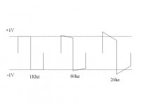
OK. I think I have ruled out power supply sag. The response is the same even unloaded. Below I will a post a drawing of what the issue looks like. I have also done more testing to confirm this.
So based on that, here is my theory!
All power supplies form an R/C network! There is always a resistance in the transformer, even at DC. Then we put caps on to smooth the output after it is rectified. Forming an R/C network. A simple 6db roll off at a frequency I will call "X"
Now I believe, in my circuit I have 2 power supply R/C circuits. Let's take a look at them.
First is the power transformer and smoothing caps. If we guess at the transformers resistance at 1 ohm and we know the smoothing caps are ~10,000uF we have at turnover frequency of ~15.9hz to be known as "X1".
Now let's take a look at the isolated supply for the FE board. 22 ohms and 470uF in that supply. A quick check of the calculator gives us a turnover frequency of ~15.4hz known as "X2".
I believe the diodes are providing isolation and thus make this a valid theory.
So if this is true we have X1 and X2 at about the same frequency. 2 poles at the same frequency generally means trouble. This may be the cause! Yet because of the widely differing C and R values of each power supply filter, we must assume that there is a large difference in phase response between the 2 filters. Think about it! There are infinite possible solutions that will create an ~15.5hz turnover frequency. So the difference must be phase!!!!!!!!!!!!!!!!!! The amplitude roll off of "X1" and "X2" are close to the same. However the phase difference must be large, based on the large differences in the R and C values to make the turnover ~match!
So I have 3 possible solutions, as I see it!!!!! Stager the turnover frequencies or change the phase differences of the filters, or remove the diodes and hope that I will be looking at an RCRC filter.
I have thought too much for tonight and will try a couple of simple solutions tomorrow to see if I can prove my theory.
Thanks. Don
Attachments
traderbam said:Don, what is the peak and trough psu voltage for both rails?
73.5 peak and 73.46 trough for both rails at ~340mA's idle.
Is my theory completely out of wack? I have not had a chance to test it! I had a wee bit of the devil's brew when I came up with it. Good stuff I think! Beer that is!!! I don't know about my theory?
Thanks, Don
Thanks, Don
Hi Don,
Can you confirm that when the output is doing that low power slopey squarewave thing that the psu ripple is the same?
I think much of what you say in your theory is right. The phase shift caused by two poles of the same f will be the same, about 45 deg at the pole f.
The FE psu only "sees" the main psu when the diodes are conducting. This will be pretty briefly each 60Hz cycle though...the ripple on this supply should be <0.5V.
So I think it is ok to treat the FE psu Z as approximately a 470uF cap. and don't worry about the impact of the main psu Z.
The O.L. gain of your circuit ought to be mainly affected by the FE circuit. So it is something about the FE circuit that is most likely to be causing the slopey squarewaves. I would be surprised if it is the FE psu...but have a look on the scope and see if anything looks weird.
Traderbam, I will look at the output stage supply and the FE stage supply and will look to see if something seems strange. I might not get to it 'til tomorrow.
I would think that if the R/C values to get to the same pole f are different that the phase characteristics would be very different. Maybe that is not the case! Just guessing!
Thanks, Don
I would think that if the R/C values to get to the same pole f are different that the phase characteristics would be very different. Maybe that is not the case! Just guessing!
Thanks, Don
Hi,
a single pole high pass filter is 90 degrees out by the time it gets to infinite frequency.
At the F-3db frequency it is 45 degrees.
Cascade two high pass single pole filters and at the same F-3db frequency the voltage will be 6db down and the phase will be 90degrees. The cascaded filters will have a Q~=0.5 (Bessel) instead of 0.71 (Butterworth).
Thanks, Andrew!
Looking at my drawing above, do you have any idea as to what is causing this. Notice that the leading edges of the waveform overshoot the target of 1 volt as the frequency decreases.
Thanks, Don
Looking at my drawing above, do you have any idea as to what is causing this. Notice that the leading edges of the waveform overshoot the target of 1 volt as the frequency decreases.
Thanks, Don
Go and look at your LF plot again.Don S said:Thanks, Andrew!
Looking at my drawing above, do you have any idea as to what is causing this. Notice that the leading edges of the waveform overshoot the target of 1 volt as the frequency decreases.
Thanks, Don
Measure the length of the vertical transition from -ve to +ve or from +ve to -ve and you will find that it is equal to or less than the 1V *2 that you are aiming for. There is no overshoot.
Is it possible that the scope has a high pass filter that is causing this distorted waveform?
Andrew, I have the scope set to DC input, and the probe is DC coupled. It also shows up as clipping at high output levels as the frequency is lowered from 100hz without any signs of clipping. With a sinewave at clipping as you lower the frequency the clipped or flat part of the waveform shows a dimple right in the middle. This gets more pronounced as the input frequency goes lower.
Thanks, Don
Thanks, Don
AndrewT said:Have you looked at ripple on the supply lines on the amplifier PCB?
Andrew, I have checked the main rails and found 40mV P2P of ripple voltage at idle. The entire output stage, including drivers uses copper buss bars for power, no pcb power traces. I have not looked at the FE board supply on the actual traces, just by the R/C filter for the FE.
Thanks, Don
I tried to see if it might be power supply related today. I bypassed the FE board diodes, no change. Next I bypassed the 22R resistors after the diodes, no change. Next I bypassed both the diodes and resistors, no change.
That shoots my power supply frequency corner theory down!!!!!!!!!!!
Nothing changes the tilt. With the circuit unloaded it is the same as with the circuit loaded. Even loaded at different power levels, still the same tilt. I think that should rule out the power supply! If the power supply was the issue it should change with load and output power.
I even changed the balance of the LTP, it made no difference!
I just don't know what it is or what to look for. What can be causing this? Help! Anyone? Everyone?
Idea's
Thanks, Don
Hi Don,
It appears as though the gain is changing. The only thing that may do this easily is the feedback network or a massive change in your circuit's operation. When this occurs, do all your LED's remain lit with no flickering? What you may have to do is break your feedback network and use a DC servo for offset. Then you can probe through each stage to see where the problem begins. You can do this with the feedback connected, but this requires more skill and both probes.
-Chris
Chris, all the led's are lit solid, even into clipping at all frequencies. DC offset is stable +-15mV's at idle.
All I can see is the effect, but not the cause.
Andrew T, made a good point that saying the gain is still the same. Look at my drawing of the scope shots. The leading edges are still 2V's total. So I think it is not a gain change. Wouldn't this show up as a rise in amplitude on a sinewave at lower frequencies if it was?
Let's say the DC offset is modulated by a low frequency squarewave. Whatever is causing it is very linear, or at least logarithmic, no erratic behavior. What might be causing it, and why do the low frequency sinewaves look just fine? No gain change, shape change, well you get the point.
I don't think that a DC servo will fix the problem. The issue is happening at too high a frequency for it to have any effect at audio frequencies. Or at least it shouldn't.
Why won't my completely DC coupled circuit behave as it approaches DC!!!!
Thanks, Don
P.S. Chris, maybe you could you call out the big dogs to help?
P.P.S. I wish I could find a way to make it to The Burning Amp this year!!!!!
- Status
- Not open for further replies.
- Home
- Amplifiers
- Solid State
- EF Output Stage