Hi Don,
Your square wave trace looks as though it is suddenly collapsing, the tail looks like a capacitor discharging with a constant current after so many msec. The easiest way to find the problem would be to run a square wave in to see where this distortion first appears. With feedback, it will show up straight away. That's why breaking the feedback network will make it easier.
Too bad you can't make it to Burning Amp. Sounds like it might be fun for all.
-Chris
It's only needed if you were to open the feedback loop. You need it to control your DC offset just so you can run the amp while testing.I don't think that a DC servo will fix the problem.
Your square wave trace looks as though it is suddenly collapsing, the tail looks like a capacitor discharging with a constant current after so many msec. The easiest way to find the problem would be to run a square wave in to see where this distortion first appears. With feedback, it will show up straight away. That's why breaking the feedback network will make it easier.
Too bad you can't make it to Burning Amp. Sounds like it might be fun for all.
-Chris
That's progress. 🙂I think that should rule out the power supply!
So what is wrong with the amp itself? You know that even though it is entirely dc coupled it shows a slope response at low frequencies that looks similar to the circuit not being dc coupled at all. In fact, the output waveform would be what you would expect if the amp actually had a feedback shunt cap or a dc servo circuit.
Are you sure it doesn't?
What else would have the same effect?
The signal generator output is directly coupled to the amps input. When I bought the generator I checked all it's functions an saw no tilt. It tested just fine in all functions, at all frequencies. I will retest it now to see if there is a problem now.
As for coupling caps, feedback caps, or servo's, look at the circuit. I designed it, made the boards myself, and stuffed the boards too. So I know it is assembled as per the schematic, which is an as built drawing reflecting the changes I had to make fine tuning it.
If it walks like a duck, and quacks like a duck, it's probably a duck!
I just don't see where it is AC coupled.
Thanks, Don
Now you've ruled out the PSU and the T&M equipment you'll need to do some surgery. The basic approach is to simplify the thing until it has no choice but to work as expected. Forget sound quality for now. Going back to my earlier post I listed a number of steps to simplify the FE stage and make sure it is super stable. You may not realise this but instability doesn't always show itself as HF ringing, sometimes it can show itself as LF dc offsets and other effects as the transistors struggle to find a happy equilibrium.
Do one thing at a time and then see what happens to the slopeyness. This is a little painstaking but the best way to identify the cause.
Do one thing at a time and then see what happens to the slopeyness. This is a little painstaking but the best way to identify the cause.
Well I am more than a little embarassed to admit this, but my lab preamp was the problem. Yesterday I went through all the test equipment I was using to verify proper operation. I had tested it for use some time before and it was working fine! I am sorry to have troubled everyone over my stupidity!
The amp is fine and tests flat to 0.2HZ. The limit of my signal generator. No tilt what so ever with or without a load at any frequency.
Boy do I feel dumb. Sorry guys and girls!!!!!!!!!
Thanks, Don
The amp is fine and tests flat to 0.2HZ. The limit of my signal generator. No tilt what so ever with or without a load at any frequency.
Boy do I feel dumb. Sorry guys and girls!!!!!!!!!
Thanks, Don
Hi Don,
do you have a dual channel scope?
Always compare input signal to output signal to eliminate errors and mis-reading.
I use an adjustable attenuator on the input, set it to match exactly the gain of the amp. Then I have the same signal on the input of the attenuator as comes out of the amplifier. That is until I run out of input drive voltage and then I have to cheat.
I have several preamps😀
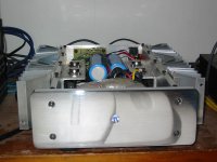
The one I was using last night is a Chinese knockoff of a Marantz 7C. I couldn't build it for $168US. I stole it out of one of my other systems. Where it was connected to a pair of monoblock Pass A40's I built. (See picture below) The A40's drive a pair of B+W CDM1SE's.
The speaker I was using last night was a Vandersteen Model 1.
I guess my next project after this one is fixing the lab preamp.
Thanks, Don
Attachments
- Status
- Not open for further replies.
- Home
- Amplifiers
- Solid State
- EF Output Stage