Mhenschel,
Yes, it has an ellipse tool. Mostly CAD is taking 2d shapes and pulling them into 3d shapes. Sometimes you need ten 2d sketches to create your single 3d object.
What is it you want made or want to test?
Yes, it has an ellipse tool. Mostly CAD is taking 2d shapes and pulling them into 3d shapes. Sometimes you need ten 2d sketches to create your single 3d object.
What is it you want made or want to test?
I was reacting to your post 40.
if you need a whole project... enclosure included then what I'm working on is a FHXL with an Alpair 10.3M and considering the larger thumbnail.
but of course I'm also keen to get a handle on the efficacy of the multi-radii (elliptical) round over with a baffle thickness limit of ~3/4".
general applicability...
By this reasoning, a driver mounted in the end of a close fitting cylindrical tube is optimal (?)If you start adding roundovers immediately beside the driver, the main diffraction hump starts to flatten out the bigger the rpubdover radius and DI decreases a bit, so could be a good thing. Overall, minimal baffle without any roundover leaves listening window pretty much clean from edge diffraction related interference. Basically the edge that radiates as secobd sound source, is so close to the driver (compared to wavelength), that it's pretty much same radiation as the driver itself.
Optimal maybe not but low diffraction for sure.
I already tried what you describe in mtm with pvc tubing/pipes as box and 2x 6'5" driver+ tweeter, sealed. It needed a lot of eq to compensate for the very high bsc, had issue with internal standing wave but once 'tolerable' ( tube fullfilled with absorbing material) it was one of those 'disapearing' loudspeaker. Very low hint of the presence of the loudspeaker itself.
I already tried what you describe in mtm with pvc tubing/pipes as box and 2x 6'5" driver+ tweeter, sealed. It needed a lot of eq to compensate for the very high bsc, had issue with internal standing wave but once 'tolerable' ( tube fullfilled with absorbing material) it was one of those 'disapearing' loudspeaker. Very low hint of the presence of the loudspeaker itself.
Published in 1951...
https://www.aes.org/aeshc/pdf/how.the.aes.began/olson_direct-radiator-loudspeaker-enclosures.pdf

And radiator size vs. baffle dimensions is important too, published in Tim Mellow & Leo Karkkainen, "A dipole loudspeaker with balanced directivity pattern", J. Acoust. Soc. Am. 128 (5), November 2010, pp. 2749 - 2757 https://www.linkwitzlab.com/models.htm

https://www.aes.org/aeshc/pdf/how.the.aes.began/olson_direct-radiator-loudspeaker-enclosures.pdf
And radiator size vs. baffle dimensions is important too, published in Tim Mellow & Leo Karkkainen, "A dipole loudspeaker with balanced directivity pattern", J. Acoust. Soc. Am. 128 (5), November 2010, pp. 2749 - 2757 https://www.linkwitzlab.com/models.htm
Last edited:
@krivium
I am confused. Doesn't the results of Olson posted by Juhazi above, show that a driver mounted in the cylinder end (C) is the worst possible for diffraction effects on the frequency response? How is this low diffraction? Am I missing something?
I am confused. Doesn't the results of Olson posted by Juhazi above, show that a driver mounted in the cylinder end (C) is the worst possible for diffraction effects on the frequency response? How is this low diffraction? Am I missing something?
Nope, driver mounted on a big sphere is optimal in this regard*, but the close fitting cylinder would not be too bad either. Bafflestep would be higher in frequency the smaller the baffle, so this might be something to consider on a realworld project. This can be though conversely, use as big driver as possible 😉 and condensed into rule of thumb, have as little flat baffle around transducer as possible, which includes situation with any sized roundover, even non-existing one.
Practical tip here is that even if the big roundovers are best (sphere), they are hard to manufacture at home. Roundovers can be approximated by cutting slants / facets to a speaker box to bring edge closer to tweeter (if it's on same baffle as a woofer), or one could opt for the smallest possible baffle, for example using different structure for the tweeter and woofer, put your tweeter on top of your woofer box! Lots of possibilities how to juggle things around avoiding the worst possible locations = long distance from any particular driver to edge (relative to driver bandwidth = wavelength).
5cm distance from 1" dome to edge makes a lot of this kind of diffraction issue into listening window in the tweeters bandwidth, but 5cm distance from 15" midrange driver hardly makes a difference. It's all relative to sound wavelength, high frequencies have very short wavelength, low frequencies very long. All of our speaker boxes are about midrange in size. I'm about 190Hz tall and so on. It really helps to think sound with wavelength rather than frequency, so better start training yourself to see physical objects and sound relate to each other, through wavelength! When wavelength is about the size of an object, the object has strong influence on the sound acoustically. 10cm object has strong influence on 10cm sized sound, and 100cm object has equal influence on 100cm sound, but the 10cm object would be invisible to 100cm sound and make no difference!🙂
*) Typically when people talk about edge diffracton being an issue, it's the backwave that emits at the edge toward listening window what makes a problem. Diffraction we cannot avoid, it simply means sound goes around an object, but we can reduce effects of the backwave that emits at the edge, basically reduce it's amplitude and delay by manipulating the edge. This secondary sound source is delayed and flipped polarity, and different frequency response, than the direct sound and audibility of it can be more or less important depending on bandwidth, but what we usually see it is ripple in the frequency response, especially on-axis. Some people off-set drivers from center of the baffle to sides to flatten the on-axis response ripple, but all they do is move the ripple to off-axis, the problem, the edge, didn't disappear. If mic is moved a little the ripple is there. More over the ripple is now different both left and right and it's just the same mess it was driver centered on the baffle.
Quick examples below, but anyone should do these kinds of excercises on their own to build intuition for objects and wavelenght!🙂 these are really fast to do in VituixCAD diffraction tool with ideal drivers, just to get intuition how wavelength and physical object size and shape relate. And to learn about sound in general, what the graphs show as they are sound visualized. Then go and build things and try to start connecting visual graphs to perceived sound to really get into this thing. Because, even if the graphs show this kind of issues, do you actually perceive (hear) them? How to make a listening test to perceive them? What should I actually perceive? and the thought process and perception starts to convert and your listening skill goes up with knowledge on graphs and all your audio hobby with it.
The examples:
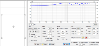
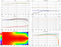
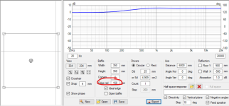
Ideal tweeter middle of big baffle to illustrate effect of the backwave on the edge toward listeing window. The bandwidth where problematic sound is, is roughly from baffle size wavelength to transducer size wavelength. View on diffraction sim so you can replicate the experiment. Then just export with "Feed driver" ticked to see the stuff in the main program, polar graphs. See how the on-axis response has wild ripple to it, even though the transducer here is ideal with flat response from DC to light. Basically the whole listening window is riddled with this (CTA 2034 defines listening window from -30 to +30deg).
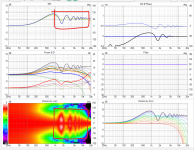
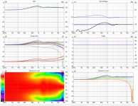
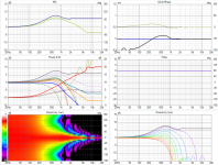
Now if I just start increasing roundover. 50mm, 100mm and 150mm here. 150mm roundovers make it almost a sphere already so no ripple. Roundover has input in the diffraction tool, that's all I've changed here.
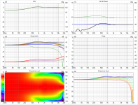
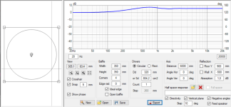
Now what if the source was size of the baffle? and roundover 0?😀 Directivity is very different because the transducer is bigger, but also there is (almost) no ripple in listening window! no diffraction related issue. This is about the performance driver being end of a tube, and last image above is driver being on a sphere, which is much better, but this ain't that far behind regarding edge diffraction ripple in listening window.
Practical tip here is that even if the big roundovers are best (sphere), they are hard to manufacture at home. Roundovers can be approximated by cutting slants / facets to a speaker box to bring edge closer to tweeter (if it's on same baffle as a woofer), or one could opt for the smallest possible baffle, for example using different structure for the tweeter and woofer, put your tweeter on top of your woofer box! Lots of possibilities how to juggle things around avoiding the worst possible locations = long distance from any particular driver to edge (relative to driver bandwidth = wavelength).
5cm distance from 1" dome to edge makes a lot of this kind of diffraction issue into listening window in the tweeters bandwidth, but 5cm distance from 15" midrange driver hardly makes a difference. It's all relative to sound wavelength, high frequencies have very short wavelength, low frequencies very long. All of our speaker boxes are about midrange in size. I'm about 190Hz tall and so on. It really helps to think sound with wavelength rather than frequency, so better start training yourself to see physical objects and sound relate to each other, through wavelength! When wavelength is about the size of an object, the object has strong influence on the sound acoustically. 10cm object has strong influence on 10cm sized sound, and 100cm object has equal influence on 100cm sound, but the 10cm object would be invisible to 100cm sound and make no difference!🙂
*) Typically when people talk about edge diffracton being an issue, it's the backwave that emits at the edge toward listening window what makes a problem. Diffraction we cannot avoid, it simply means sound goes around an object, but we can reduce effects of the backwave that emits at the edge, basically reduce it's amplitude and delay by manipulating the edge. This secondary sound source is delayed and flipped polarity, and different frequency response, than the direct sound and audibility of it can be more or less important depending on bandwidth, but what we usually see it is ripple in the frequency response, especially on-axis. Some people off-set drivers from center of the baffle to sides to flatten the on-axis response ripple, but all they do is move the ripple to off-axis, the problem, the edge, didn't disappear. If mic is moved a little the ripple is there. More over the ripple is now different both left and right and it's just the same mess it was driver centered on the baffle.
Quick examples below, but anyone should do these kinds of excercises on their own to build intuition for objects and wavelenght!🙂 these are really fast to do in VituixCAD diffraction tool with ideal drivers, just to get intuition how wavelength and physical object size and shape relate. And to learn about sound in general, what the graphs show as they are sound visualized. Then go and build things and try to start connecting visual graphs to perceived sound to really get into this thing. Because, even if the graphs show this kind of issues, do you actually perceive (hear) them? How to make a listening test to perceive them? What should I actually perceive? and the thought process and perception starts to convert and your listening skill goes up with knowledge on graphs and all your audio hobby with it.
The examples:
Ideal tweeter middle of big baffle to illustrate effect of the backwave on the edge toward listeing window. The bandwidth where problematic sound is, is roughly from baffle size wavelength to transducer size wavelength. View on diffraction sim so you can replicate the experiment. Then just export with "Feed driver" ticked to see the stuff in the main program, polar graphs. See how the on-axis response has wild ripple to it, even though the transducer here is ideal with flat response from DC to light. Basically the whole listening window is riddled with this (CTA 2034 defines listening window from -30 to +30deg).


Now if I just start increasing roundover. 50mm, 100mm and 150mm here. 150mm roundovers make it almost a sphere already so no ripple. Roundover has input in the diffraction tool, that's all I've changed here.


Now what if the source was size of the baffle? and roundover 0?😀 Directivity is very different because the transducer is bigger, but also there is (almost) no ripple in listening window! no diffraction related issue. This is about the performance driver being end of a tube, and last image above is driver being on a sphere, which is much better, but this ain't that far behind regarding edge diffraction ripple in listening window.


Last edited:
Hi, yes, I was about to post about this 😀 Difference with olson paper is that it uses very small transducer on big cylinder! The Olson image posted around forums only shows small transducer on big baffle, and that roundover really makes difference there. But if the baffle is small relative to transducer, most of the geometries are impossible to make first of all, and the ones that are possible have no ripple as in the image, so it's incomplete illustration of the phenomenon!@krivium
I am confused. Doesn't the results of Olson posted by Juhazi above, show that a driver mounted in the cylinder end (C) is the worst possible for diffraction effects on the frequency response? How is this low diffraction? Am I missing something?
Please, I really urge everyone do their own research and conclusions using some diffraction simulator, as it's real time and really easy to experiment and teaches a lot about wavelength and how sound reacts with objects!
ps. note that Olson paper shows ripple due to diffraction from back edge as well, this is not possible to simulate in VituixCAD simplified flat baffle sim, but hear me this: the front edge, the physical structure size and shape right beside the transducer makes most effect to response in listening window just because SPL there is much greater than at the back of the box. What happens after the first "edge", like at the back of the box, has also some effect on listening window, but these are second order effects and have less influence simply because amplitude is way smaller there but also direction of the backwave is different so it mostly affects far off-axis. While diffraction makes sound go all the way around the box, and backwaves here and there, they might be audible and it's worth to consider further cleanup speaker response by shaping the backside, they are still secondary effects and way less important than what happens in the front.
Last edited:
@krivium
I am confused. Doesn't the results of Olson posted by Juhazi above, show that a driver mounted in the cylinder end (C) is the worst possible for diffraction effects on the frequency response? How is this low diffraction? Am I missing something?
Diffraction issues with box are 2 main kind: 'baffle step' then 'edge diffraction'.*
As can be seen from Olson works with a minimal (or no baffle at all and a circular driver) then baffle step is at it's worst. Hence my comment about the pipe experiment needing a lot of eq to compensate for bsc and it was centered circa 700hz if memory serve. Overall the whole bandwith of woofer was under influence of eq ( xover to tweeter circa 3khz).
Edge diffraction on the other hand seemed to be very low and ime/imo this is what makes loudspeakers box audible ( freq range in which it happens + level of secondary emmission).
If you can try it by yourself: use strings to elevate a full range driver and play it as is. Use dsp to counteract bsc, it the easiest way. Of course the dipole play a role too but it won't affect too much diffraction.
In my experiment i had to ask a friend to make a ring out of wood to have the driver fixed into the pipe. It was a lot of hassles imho.
Edit: Tmuikku explanation above explain it better maybe?
* there is a 'grey' area in between of course.
^yeah same thing in different words! not sure it's better, just more words🙂 People think differently, so multiple different wordings for same phenomenon have better chance to ring more bells.
By my understanding, baffle step is responsible for fall of the decreasing frequency on axis response, but the severe ripple with increasing frequency is due to diffraction.Diffraction issues with box are 2 main kind: 'baffle step' then 'edge diffraction'.*
As can be seen from Olson works with a minimal (or no baffle at all and a circular driver) then baffle step is at it's worst. Hence my comment about the pipe experiment needing a lot of eq to compensate for bsc and it was centered circa 700hz if memory serve. Overall the whole bandwith of woofer was under influence of eq ( xover to tweeter circa 3khz).
Edge diffraction on the other hand seemed to be very low and ime/imo this is what makes loudspeakers box audible ( freq range in which it happens + level of secondary emmission).
For completeness, here is offset driver. I tried to make the on-axis response as good as I could moving the transducer, and diffraction related issue gets better, ripple spreads out and averages out better, but still the response varies to all directions so the "problem" is still there. This is easiest to manufacture though in a real world, a showbox, tweeter not in the centerline of the baffle.

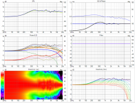
Few images from the previous examples for comparison. Driver in the middle, and then with proper as big as fits roundover. Which one of these three fixes the "problem"?
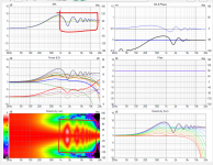
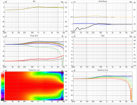


Few images from the previous examples for comparison. Driver in the middle, and then with proper as big as fits roundover. Which one of these three fixes the "problem"?


I am having difficulty accepting the argument that edge diffraction only becomes a problem when the baffle size is comparable to the transducer size.Now what if the source was size of the baffle? and roundover 0?😀 Directivity is very different because the transducer is bigger, but also there is (almost) no ripple in listening window! no diffraction related issue. This is about the performance driver being end of a tube, and last image above is driver being on a sphere, which is much better, but this ain't that far behind regarding edge diffraction ripple in listening window.
For example, consider a mid-range transducer, since we are most sensitive to mid-range frequencies. Then the transducer is definitely not modelled as a point source. Assuming ideal pistonic motion and no surround restriction, sound (acoustic pressure/rarefaction) waves are generated everywhere adjacent to the cone/diaphragm. These acoustic waves travel outward in a spherical wave front. In the extreme case, acoustic sound will travel from one side of the diaphragm along a diameter to the opposite edge. Such an acoustic wave has travelled a distance exactly equal to the size of the driver. If the driver is in an identical diameter cylinder with zero roundover, surely extreme diffraction effects should still be apparent? 🤔
I don't think it will be correct to ignore the effect of signals generated by distinct parts of the cone/diaphragm because this is exactly what is relevant when analysing cone break-up/resonance (non-pistonic) behaviour.
..or maximum diffraction when there is no baffle?Optimal maybe not but low diffraction for sure.
There is also minimum directivity control.
Simulations use flat disc with pistonic movement. Some simulations can use edge chamfering or rounding and a box.
The Edge is my favourite sim. https://www.tolvan.com/index.php?page=/edge/edge.php
Typical loudspeakers are cones or domes and they do behave differently when wavelength is shorter than disc diameter. Also edges (surround and frame) cause diffractions at high frequencies. https://www.klippel.de/fileadmin/_migrated/content_uploads/KLIPPEL_Sound_Radiation_Poster_01.pdf
Placing the transducer off from center changes diffractions, but always asymmetrically when measured off-axis.
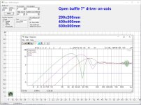
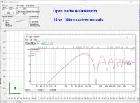
But hey, this thread is just about edge rounding effects!
The Edge is my favourite sim. https://www.tolvan.com/index.php?page=/edge/edge.php
Typical loudspeakers are cones or domes and they do behave differently when wavelength is shorter than disc diameter. Also edges (surround and frame) cause diffractions at high frequencies. https://www.klippel.de/fileadmin/_migrated/content_uploads/KLIPPEL_Sound_Radiation_Poster_01.pdf
Placing the transducer off from center changes diffractions, but always asymmetrically when measured off-axis.


But hey, this thread is just about edge rounding effects!
Last edited:
-
..or maximum diffraction when there is no baffle?Optimal maybe not but low diffraction for sure.
There is also minimum directivity control.
allenB comes in that diffraction is maximized, like always, nice bridge to Bon's post. Diffraction means sound going around object, it is not a problem, sound that goes away from the speaker is not a problem, only the back wave that emits at the edge might be.
Bon, you are right, diffraction always happens, sound would always go around objects, with the minimal baffle as well and as Allen argues it diffracts more!🙂 But is it problematic? I do not ignore this and wrote about it, that the main diffraction hump still remains with minimal baffle.
On forums and in loudspeaker context in general edge diffraction is usually associated with the interference pattern seen in listening window. This is due to back wave that emits at the edge when sound diffracts around the corner. This secondary sound source has delay to it and interferes with direct sound so that it makes distinct ripple in the response which changes with observation angle. This would happen on all wavelengths maybe 10x baffle size and shorter, but the interference is uniform to all angles on long wavelengths, and wavelengths smaller than baffle dimensions are the main issue that is typically talked as edge diffraction. AllenB always comes and bites with this detail.
So Bon, what you want to consider as bad or problematic diffraction? This is important in order to understand what I'm referring to with the above posts. I wrote what I think is the problematic diffraction, the ripple on shorter than baffle wavelengths, and that main diffraction hump that remains with minimal baffle is not, except if you want low DI system.
So diffraction happens with minimal baffle as well, and back wave emits at the edge. Important bit here is, that this is still at wavelength that doesn't make response vary per angle: short wavelengths that would make the response vary per angle, which would make the problematic diffraction related interference, are beamed by the driver and very little goes toward the edge, thus we don't see much interference at all! Actually response varies per angle, but smoothly due to only long wavelengths are loud enough to make difference. We see boost in on-axis response and reduction off-axis on the main diffraction hump, so higher DI, but no ripple frequencies above that. Sometimes this is a feature that is wanted, higher DI. Sometimes it is not, so then it could be problematic for you. If it is, then try to mitigate it by making your structure a sphere.
Sound works as you point out, any point on the cone surface can be though as point source and they all emit at the same time assuming pistonic transducer. Driver beaming is due to what you point out. If you take any two points, one from each side of the cone for example, and use wavelength and observation angle and distance you can calculate path length difference and how they superimpose. This is exactly why (ideal) drivers beam. You can do this thought experiement with the edge diffraction as well, to simplify you can average all points on the cone as one point in the center.
Last edited:
Then it seems I have your attention, though I'd rather have your thoughts on the issue 😉AllenB always comes and bites with this detail. So Bon, what you want to consider as bad diffraction? This is important in order to understand what I'm referring to with the above posts.
Arguments supporting your view would include geometry and timing. Reducing the baffle area may reduce response variations even for a similar amount of diffracted energy, so polar plots are not going to clearly show the amount of diffraction. They may even show little variation when the diffraction may be audible. Then, what measurements would you use to readily spell out the other properties of the diffraction?
Last edited:
- Home
- Loudspeakers
- Multi-Way
- Edge Diffraction Testing - Shapes