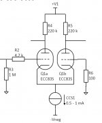
Recently, I build an EL84 PP amp with a ECC83 differential amplifier as preamp with the following characteristics:
- Supply voltage (+V1): 300 V DC
- CCS: Cascode FET circuit
- Max output swing: 24 Vp-p
The end stage is coupled through a 0.1 mu caps and the input resistance of the end stage is approx. 300 - 1000 kOhm.
I have simulated and tested this circuit and it works nicely. I did have to adjust one of the two plate resistor values to match the bias current in the two amp halves.
My next step if to further investigate performance in detail (IMD, bandwidth, impact of plate load (due to end stage), etc).
I'm very interested to learn if people have experience with optimising such a preamp and if there are any ideas/suggestions how to further improve.
Thanks
Attachments
I would restrict your bias adjustment to the cathode of the ECC83's. A 100R wire wound pot with the wiper to the CCS would do just the job. Also the resistance would help to stabalize the DC operating point (bias) of the circuit.
It seems that DC and AC balance are not the same and if you get the DC balance right the AC balance at the plates will probably be out. Only adjustment using a scope can get the AC balance right at the cost of DC imbalance. The reality is that this will drift over time so the adjustment would need to be at regular intervals.
In my experience such precautions are not really that important as the slight differences are reintegrated within the output stage and output transformer and it has very little effect on the sound of the amp between valve changes.
Shoog
I remember an experiment by SY using two very different tubes (like half ECC82 and half ECC83) in a differential/LTP stage, and given the plate resistors were matched, the AC balance was kept perfect, but of course DC not. Still I don't remember the details.
how I dared to mention SY working with ECC82 😀 Sorry!
I didn't realize that they behaved quite this well AC wize - very impressive.
No special attention needed to match the valves or balance the DC then.
Shoog
DC balance issues in real life can come from triode matching.
DC balance issues in simulation (and real life) can come from grid current. The two grids see very different DC conditions: 1M and 100R in your circuit. The classic Mullard DC-coupled LTP has the same trouble, although there it is the second triode which has the high DC resistance on its grid.
The ECC83/12AX7 has only a narrow window between grid cutoff and grid current. This is because it is a high gain, high impedance valve. If the anode voltage drops too low then in order to maintain the required anode current (set by the tail) the grid voltage has to rise and can enter the grid current region. Bear in mind that simulator valve models might not do grid current particularly accurately - some omit it, others may err on the side of caution, and none can know exactly how much gas or exactly what chemical potential (?) your valve electrodes will have.
Hi all, thanks a lot for your input. I need some time to digest all, but please find my initial fb below.
@ Shoog: I assume the 100 R pot is used to increase the local feedback (similar as used for transistor diff amps). I'm aware that the amp is as good as it's weakest link, but I need to understand the details to know what the weakest link is ;-)
@ SY: Food for thought 🙂 As said before, need some time to study further
@ JazBo8: THD is quite good already, at the moment IMD and bandwidth has my focus. FYI: I'm not using global/overall fb
@ DF96: The DC conditions are different. I realise the 1M is actually 100 k due to the volume pot. Increasing the 100 R value reduces the high frequency range. Do you have any rules of thumb or formulas to manually check if this so called grid current region is entered?
The wire wound pot offers the option to balance the DC bias points, but evidently there is little benefit to be gained by doing so.
Shoog
Shoog
The clear sign is that well-matched triodes (probably identical in simulation) with identical anode and cathode circuits, but different grid circuit resistances, have different anode voltages. Reducing the anode voltage, or increasing the anode current, increases the imbalance.Koektrommel said:Do you have any rules of thumb or formulas to manually check if this so called grid current region is entered?
The solution is to reduce the anode current or raise the anode voltage. A cathode balance pot, as suggested by Shoog, can hide the problem as it doesn't distinguish between triode parameter imbalance (OK) and grid current (not OK). The problem with grid current is that it can add a non-linear load to the source, so introducing distortion.
Do you have any rules of thumb or formulas to manually check if this so called grid current region is entered?
Empirically, you start seeing this effect below about 1V cathode-to-grid in 12AX7/ECC83.
Hard to say since we have no clue as to how the circuit is being used. Any extra info you can give us would be helpful.
With two low-distortion valves connected in a low-distortion circuit too much IMD means either too much signal or a design error. Plot your design on a mutual characteristics chart, or simply look at the point occupied by the quiescent triode. If Vkg is less than about -1V in order to get your chosen anode voltage and current then you have grid current problems. If your input signal is likely to swing you into this region then you will get problems too even if the quiescent point is OK.
This is why the fashion for using ECC88's in low voltage preamps/buffers is such a bad idea - they always end up drawing grid current and destroying the volume pot.
Shoog
Shoog
You mean 83's? However, I suppose 88's might have a similar problem as they too have quite a high gm/Ia ratio.
My first ventures into valves were using ECC88's at low voltage, and they all had scratchy volume pots after a few months of use.
Shoog
Shoog
Yes, a very small DC current can weaken a pot. Yet circuits regularly appear with direct grid to pot connections. Some people seem determined not to learn from others.
- Status
- Not open for further replies.
- Home
- Amplifiers
- Tubes / Valves
- ECC83 differential preamp optimisation