Sorry, slightly OT, but how does one go about optimizing IMD using SPICE? I have tried to digest what was mentioned on the SPICE thread, but want some one that has done it to verify:
Here is what I gathered: run two tone, say 19.5K and 20.5K and perform fourier analysis at 1K with 20K window. Of course, the triode spice models need to be changed, so they are not identical (otherwise not much point to the exercise...), anything else that needs to be done? Just trying to learn to use SPICE the proper way - so please no "you can't rely on SPICE" type of comments ;-)
Jaz
Empirically, you start seeing this effect below about 1V cathode-to-grid in 12AX7/ECC83.
@ SY: Where did you derive this figure from?
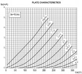
If I understand correctly, to meet the mentioned rule-of-thumb using the attached characteristics, given an input swing of 1 Vp-p and desired Ia of 1 mA, I would need a anode voltage of 240 V.
Attachments
@ SY: Where did you derive this figure from?
It's not derived, it's experimentally observed. You can reduce the effect by having very low source impedances driving the grid, but the effect is still there.
A 1V grid-to-cathode swing is usually quite unreasonable for a tube with a mu of 100!
Remember that in an LTP each grid-cathode sees only half the input swing.
You could add a grid resistor (like a grid stopper) to Spice but keep its resistance low. If increasing this resistor increases distortion then you are probably seeing grid current in action. However, avoiding this in simulation does not guarantee good results in real life, as each triode has its own grid current behaviour (which can change with ageing). Low source impedance is the only guaranteed solution.
You could add a grid resistor (like a grid stopper) to Spice but keep its resistance low. If increasing this resistor increases distortion then you are probably seeing grid current in action. However, avoiding this in simulation does not guarantee good results in real life, as each triode has its own grid current behaviour (which can change with ageing). Low source impedance is the only guaranteed solution.
It's not derived, it's experimentally observed. You can reduce the effect by having very low source impedances driving the grid, but the effect is still there.
A 1V grid-to-cathode swing is usually quite unreasonable for a tube with a mu of 100!
Ok, understand. I only have experience with grid current measurements for EL34 and from what I remember they can vary significantly, mainly depending on manufacturer.
1 Vp-p is indeed a 'worst-case' input required to achieve max power, still having 6 dB headroom in the preamp. Just a number to start with 🙂.
I'm not a big fan of the ECC83S, but I did not yet take the time to find the right fitting parameters for other ECC83 types. Again, just a tube to start with 🙂
Your best bet may be to start from the Mullard LTP and modify it to suit your situation, while maintaining the same quiescent bias voltages. You can be sure that they were aware of how best to use it; they just 'forgot' to tell their customers about the constraints they carefully avoided. Look for any 5-10 or 5-20 amplifier circuit with voltage readings.
Remember that in an LTP each grid-cathode sees only half the input swing.
You could add a grid resistor (like a grid stopper) to Spice but keep its resistance low. If increasing this resistor increases distortion then you are probably seeing grid current in action. However, avoiding this in simulation does not guarantee good results in real life, as each triode has its own grid current behaviour (which can change with ageing). Low source impedance is the only guaranteed solution.
Yes, you are right regarding the signal swing on the cathode. That makes life a bit easier.
I haven't looked into the Spice model to understand how it models grid current. Still need to do so (and probably measure it) to start to thrust it 🙂.
If this is used for the input stage of a power amp (you still haven't clarified what this circuit is actually for), you'll have to next start thinking about what's on the other end- your plate loads at AC may be very much smaller than you are planning...
The best way to detect grid current is indirectly. Drive the grids through a large impedance and see how the distortion increases.
The best way to detect grid current is indirectly. Drive the grids through a large impedance and see how the distortion increases.
If this is used for the input stage of a power amp (you still haven't clarified what this circuit is actually for), you'll have to next start thinking about what's on the other end- your plate loads at AC may be very much smaller than you are planning.
The end-stage consists of 2x EL84 in PP connected to a toroidal OPT (VDV8020). Bias current is set using a negative grid voltage. The OPT is intended for use with 5 Ohm load, however my measurement resistor is 8.2 Ohms. Also this circuit I plan to further develop.
Yes, I am aware that 1 Vp-p is rather large and I will use different levels once I better understand the behaviour of the circuit (and where I want to take it)
Attachments
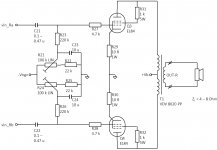
OK, so remember that your AC loadline has to have the 220k grid resistors in parallel, for an effective plate load of 110k (quite low for that tube). As well, you need to think about the Miller capacitance of the output stage and the risetime/bandwidth that will result when the very low current, high source impedance 12AX7/ECC83 tries to drive it at high frequencies.
Personally i would go with a beefier valve. 5687, ECC99 etc etc.
The original Mullard circuits were designed for low output sources where high gain was an issue to drive to full output. The modern sources have much higher output and a preamp can offer even more gain - 100mu tubes seem rather over the top to me.
Since its going to be a classy build I would be inclined to slap a input transformer up front and drive both inputs - preserving all the gain of the LTP rather than just half.
Shoog
Last edited:
The Mullard ECC83 LTP can (just) drive UL EL34. Triode EL84 might be a bit harder so do some slew rate sums.
@ SY: Thanks for your feedback so far. The bandwidth is indeed an issue which I need to resolve in the future (I am not fully satisfied with the AC load). As I understand today, increasing bias current to 1 mA or larger significantly reduces internal resistance (variations) and should therefore reduce distortion. Noise will probably increase.
To minimise the grid current I will need to decrease the value of the anode resistors (not considering the AC load for simplicity). The trade-off might be a higher distortion due to a steeper load line.
@ Shoog: It just happens that I have a huge stock of ECC83 and I thougth an amp would be a nice way to get rid of them 😀
@ DF96: Thank you too for your feedback so far!
I'm very interested to learn if people have experience with optimising such a preamp and if there are any ideas/suggestions how to further improve
Yep. Used a very similar phase splitter for this project (attached).
The 6SL7 doesn't have quite the gain of a 12AX7 (u= 70 v. u= 100). Other than that, they're similar in that both are designed for very low plate currents, and drive up the u-Factor by increasing the plate resistance.
As for performance, it's no different than it is for any triode voltage amp: load the plate as lightly as possible. This gives the best distortion performance, and a CCS plate load in the limit.
Also, these low current types like Lo-C, Hi-Z loads. That's why the project incorporates cathode follower grid drivers: to isolate the LTP from the Hi-C load of the power finals. There is a bit of design compromise here since the finals use local NFB. This increases the load at the plates, but the total plate load is still quite a bit higher than the plate resistance. This is a bit easier to accomplish with 6SL7s as the plate load (rp= 44K, nominal) is smaller than it is for the 12AX7 (rp= 90K, nominal). One reason why I prefer the 6SL7 over the 12AX7.
Attachments
As for performance, it's no different than it is for any triode voltage amp: load the plate as lightly as possible. This gives the best distortion performance, and a CCS plate load in the limit.
For me the best way to take advantage of the high mu tubes is: input phase splitting transformer and simple differential stage where I can have the CCS as a plate load. This is followed by a cathode follower in order to provide the light load. Possibly the cathode follower is DC coupled to the output stage to erase blocking distortion. The reason for this is that I can use a region of the plate curves where high mu devices are very linear but this is usually not accessible using resistive loads. In this case one can really swing plenty of volts with very low distortion. The second choice would be a cross-coupled phase inverter (+ cathode follower of course), where again I don't need a current sink, if one doesn't want to use a splitting transformer.
The DC coupled cathode follower is possibly one of the best solutions to bias and drive output tubes regardless of A1 or A2 drive. If one is not interested in A2 or AB2 it could be made with the a 12AX7 as well! Moreover the cathode follower can be used to add a pot in order to achieve dynamic balance.
Third choice is the concertina (+ cathode follower) where again the voltage amplifier can have a CCS however in this case the cathodyne phase splitter will limit the swing in comparison to other choices.
I personally consider the LTP only when I need to swing just few volts (high sensitivity output tubes or 3 stage amps).
Anyway the 6SL7 is a lot better than the 12AX7, IMHO.
Last edited:
Possibly the cathode follower is DC coupled to the output stage to erase blocking distortion. ... The DC coupled cathode follower is possibly one of the best solutions to bias and drive output tubes regardless of A1 or A2 drive. If one is not interested in A2 or AB2 it could be made with the a 12AX7 as well! Moreover the cathode follower can be used to add a pot in order to achieve dynamic balance.
Interesting, do you have a circuit to demonstrate how you realise DC coupling (Norton circuit, resistor/voltage supply in cathode end tube or other?)
This afternoon I played around with LTSpice to look into IMD. It is a quick and dirty simulation, but some interesting results. Interesting enough for me to build and test this in the near future. Attached some snapshots of the simulation results.
Attachments
Thanks for sharing your simulation results, it will serve as a good tutorial for me (and may be others as well) to do IMD analysis.
Jaz
Jaz
Interesting, do you have a circuit to demonstrate how you realise DC coupling (Norton circuit, resistor/voltage supply in cathode end tube or other?)
Hi cakebox 🙂
Take a look at this link to see how DC couple a cathode follower to an output tube. Ok, George is using a mosfet here, but you can swap that for a tube, principle is the same.
Hope this helps, Erik
- Status
- Not open for further replies.
- Home
- Amplifiers
- Tubes / Valves
- ECC83 differential preamp optimisation