Hi Eric 'the Greatest',
Thanks for sharing the link!
Very intersting and close to what I have in mind. Looks like he is using a large cathode resistor for the power tube to set the correct bias level. I will study the material in more detail this weekend.
Regards,
Jos
Thanks for sharing the link!
Very intersting and close to what I have in mind. Looks like he is using a large cathode resistor for the power tube to set the correct bias level. I will study the material in more detail this weekend.
Regards,
Jos
Hi Jos,
The bias is set by the potentiometer connected through the large gate resistor to the gate. The voltage gate - source is, within limits, constant, so if you change the voltage at the gate, the source will follow. The big resistor (from source to B-) mimics a CCS: it is chosen based on expected voltage at source minus B-, divided by the wanted standing current (if source is expected to be at -50V, B- is -400V, and one want 10mA, the value of R is (400V - 50V / 0,01A = 35k)
Best regards,
Erik
Interesting, do you have a circuit to demonstrate how you realise DC coupling (Norton circuit, resistor/voltage supply in cathode end tube or other?)
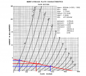
Designing this is no different from any other hollow state design: loadlines (attached). Since this is a dual rail supply of +150Vdc/-300Vdc, this is the same as:
Vpp= 150 - (-300)= 450Vdc
Use that as the basis to draw a loadline.
From the 807 spec sheet, we require Vgk= -22.5Vdc (nominal). If the cathode is sitting at -22.5Vdc, that gives one point along the loadline: Vpk= 150 - (-22.5)= 172.5Vdc. So pick off that point to determine the resulting Ipq, and Vgk for the 6SN7s. This comes to: -7.0Vdc. Since the cathode is already at -22.5V, the grid must be at: -7 - 22.5= -29.5Vdc (nominal). Since this is a cathode follower, there is a lot of leeway for adjusting the operational grid voltage, used to vary the bias to current balance the finals.
Since this is a cathode follower design, you will need the plate current maximum and minimum, and these are picked off the plate characteristic. Next, calculate the voltage across the tail resistor:
Vrtail(max)= 100(4.09)= 409V
Vrtail(min)= 100(1.68)= 168V
Calculate the actual cathode voltages:
Vrk(max)= -300 + 409= 109V
Vrk(min)= -300 + 186= -132V
Since Vgk= 0 at the current maximum:
Vi+= 109V
And Vgk= -14V at the minimum:
Vi-= -132-14= -146V
Vi= Vi+ - Vi-
Vi= 109 - (-146)= 255Vp-p
Vo= 109 - (-132)= 241Vp-p
Av= 241/255= 0.95 V/V
And done!
Attachments
This afternoon I played around with LTSpice to look into IMD. It is a quick and dirty simulation, but some interesting results. Interesting enough for me to build and test this in the near future. Attached some snapshots of the simulation results.
Some questions regarding the simulation - why are the amplitudes for Vin1 & Vin2 different (0.2 vs. 0.22)? And does R1 represent the load for the differential output? If so, why is it set so low? With ~30dB increase in IMD distortion level for the mis-matched pair, why it doesn't seem to impact the square wave response that SY posted? 😕
Jaz
Last edited:
Some questions regarding the simulation - why are the amplitudes for Vin1 & Vin2 different (0.2 vs. 0.22)? And does R1 represent the load for the differential output? If so, why is it set so low?
Jaz
The difference between Vin1 and Vin2 is a typo error, but should not make any significant difference in the results.
Both outputs are taken from the anodes. The load is the anode resistor + other circuitry connected to the preamp (usually input power stage).
R1 only shortens the 2nd grid to ground. Higher resistor values will limit the bandwidth of the preamp
- Status
- Not open for further replies.