@StevieF,
I believe to have found something that may help us. If you look at section 3.5 (schematics) of the TDA7498E datasheet, it is show how connections have to be made for PBTL-configuration. The jumpers that need to be changed are shown. I get the feeling that the jumper names (..J3, J4, J5..) in the schematics of the datasheet match the jumper names used on your board. Practical!
Try with an Ohm-meter if the jumper connections on the board match the names used in the datasheet schematics.
I can also encourage any red sanwu owner to change inductors to sagami styled one, it's way better.
I never thought it could change SQ like it did !
Thanks a lot for your reply.
I will try with my SAGAMI clones one day. I may implement the filter external of the Sanwu board such that I can use the filter to test other boards as well. Thanks for the idea.
UnrealFrench
Thanks FauxFrench, the board is on its way to me, still in China, it will take awhile till I get it. When it gets here, I'll trace out the jumper connections & provide feedback about it.
I have a red sanwu tpa3116 board on the way too, waiting patiently for them both to arrive is difficult
I have a red sanwu tpa3116 board on the way too, waiting patiently for them both to arrive is difficult
I can't seem to be able to edit my earlier post anymore. So new post.
Here's an update, I found a way to translate the text somewhat in regards to PBTL mode pic for the board I mentioned. I'll attach it again to this post for reference for others. It says this:
-------------------------------------------------------------
PBTL single channel input
(J6 jump cap inserted ,
WR - connect with WL -
WR+ and WL+ connection )
PBTL differential single channel input
(Remove R21 J6 jump cap inserted ,
WR - connect with WL -
WR+ and WL+ connect three
Volume is not controlled by electrical diameter )
---------------------------------------------------------------
As FauxFrench noticed earlier that this board closely follows the test circuit in the datasheet for tda7498e. I checked the datasheet, the input side I have mostly figured out, the output side I have a question. This is strictly in regards to the test circuit in the datasheet.
Q. In mono mode(PBTL), does [WL+&WR+] as a whole become the positive terminal & [WL-&WR-] become the negative terminal for the speaker connection?
OR
Q. Is Lout(+or-) as a whole the positive terminal and Rout(+or-) the negative terminal for the speaker connection? I dont think so but might as well ask.
Attachments

Last edited:
WL+/WR+ and WL-/WR- are before the output filter and can for that reason not be speaker terminals.
The idea with PBTL is that one of the two outputs is abandoned for the remaining output to be "stronger". You can use L+ and L- OR R+ and R- as outputs but as such not both. For the channel that is not used, the filter chokes should be removed.
Theoretically you could put a speaker on each of the two filter outputs. The speakers would have the same signal (mono) and you would have gained nothing with the PBTL coupling.
Effectively what you do with PBTL is to put the power switches in the two channels in parallel such that the parallel switches have half the impedance of the individual switches. But, then you have only one output.
Last edited:
I would prefer PBTL mode with this board because I would like to use it with just one speaker cabinet source, no stereo setup. That way I wouldn't have a need for a dummy load as well for the unused output & the added 60W(theoretical) would help. But would it be necessary to remove the filter chokes for the unused output on this board?
I'll put a dummy load of 8ohms on the R-output & ground the R-input and use the L-sides for in/out since the pic shows the left inputs for PBTL, I think I'll need a load in PBTL mode I think for this board for the unused outlet cause this one runs in mono on both outputs in that mode.
I'll put a dummy load of 8ohms on the R-output & ground the R-input and use the L-sides for in/out since the pic shows the left inputs for PBTL, I think I'll need a load in PBTL mode I think for this board for the unused outlet cause this one runs in mono on both outputs in that mode.
Last edited:
I would prefer PBTL mode with this board because I would like to use it with just one speaker cabinet source, no stereo setup. That way I wouldn't have a need for a dummy load as well for the unused output & the added 60W(theoretical) would help. But would it be necessary to remove the filter chokes for the unused output on this board?
I'll put a dummy load of 8ohms on the R-output & ground the R-input and use the L-sides for in/out since the pic shows the left inputs for PBTL, I think I'll need a load in PBTL mode I think for this board for the unused outlet cause this one runs in mono on both outputs in that mode.
I will refer to the posting of ddapkus in the TPA3116 thread. It is one of the first postings. Without a load, you risk damage in the output section. So, better remove the chokes. A dummy load at the unused output will act as a parallel load to the speaker because the two channels, when connected for PBTL, have the same output signal.
Ah! got it, thanks FauxFrench.
So relating that to the test circuit in the datasheet, I take out L1 & L2 if I'm not using R-output and I take out L3 & L4 if I'm not using the L-output. Looks easy enough to do on this board since those chokes are through hole, I can think of ideas wherein I could use a switch(es) to toggle those in/out of the circuit if needed.
Could I do the same if I wanted to run in BTL mode & not need to use the other channel? I think so..
So relating that to the test circuit in the datasheet, I take out L1 & L2 if I'm not using R-output and I take out L3 & L4 if I'm not using the L-output.
Correct!
Looks easy enough to do on this board since those chokes are through hole, I can think of ideas wherein I could use a switch(es) to toggle those in/out of the circuit if needed.
Could I do the same if I wanted to run in BTL mode & not need to use the other channel?
That configuration I do not understand. BTL mode with only one channel used leaves no advantages over PBTL mode. It is only a matter of the impedance of the output switches in the channel being used.
I've just bought this board, TDA7498 based amplifier:
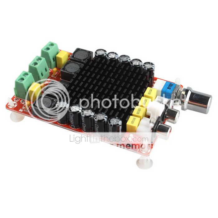
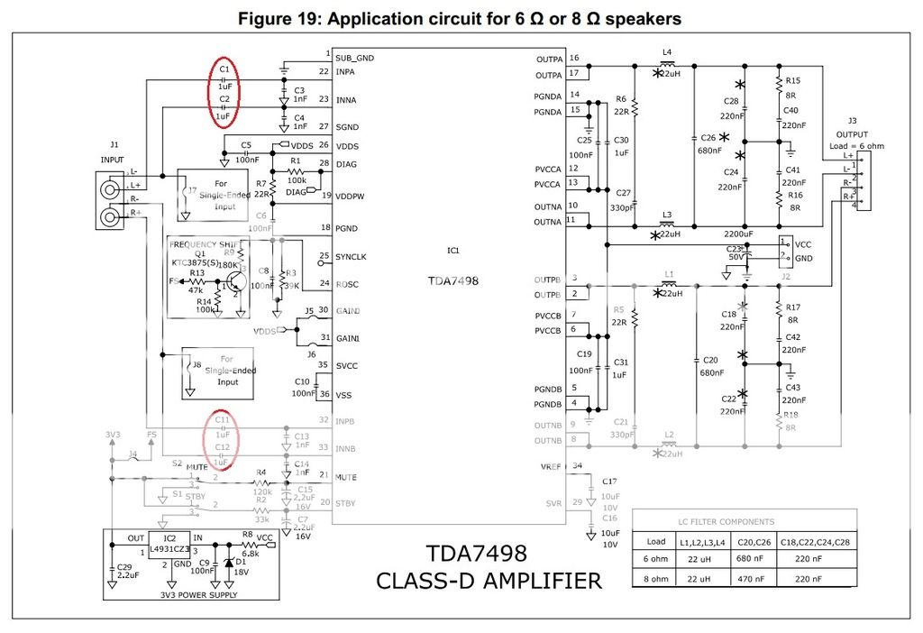
The circuit that is taken from datasheet
I'm going to try some modifications, like replace all 220uF/35v capacitors with 470uF/35v, and replace the input capacitors (value 1uF) with new ones that I think better 🙂
According to the datasheet of TDA7498 and the real board that I have, I can see 4 input capacitors. So which input capacitors do I need to replace? All C1, C2, C11, C12 or just C1 and C11?
Please help! Thank you in advance!
If you use balanced input configuration, you need to change all four (C1, C2, C11 and C12).
If you use non-balanced configuration, you do not have a varying signal on C2 and C12. Therefore, capacitor non-linearity is not a problem for C2 and C12. But, piezo-electrical effects and noise is still in play for C2 and C12. Therefore, change all four (C1, C2, C11 and C12).
If you use non-balanced configuration, you do not have a varying signal on C2 and C12. Therefore, capacitor non-linearity is not a problem for C2 and C12. But, piezo-electrical effects and noise is still in play for C2 and C12. Therefore, change all four (C1, C2, C11 and C12).
I received my Tda7498e board earlier.
I took out the chokes for the channel I wouldn't be using. There is something odd that I noticed about this board. It gives a sizzling/frying pan sort of noise on the board itself(not through the speakers). I think it goes away when a fan is connected to the on board auxiliary power outlet, although I'm not entirely sure of that.I tried using one 12V fan that has no mechanical noise but i accidentally fried it when I raised the mains input voltage & didn't check the voltage on fans supply port. After that I took another fan & used it fine but it has mechanical noise on it so i'm not sure, need to further test this so I've got two 12v & 24V fans incoming, let's see what I find. I think the frying sound is coming from the chip or chokes,I can't zone in on the source at the moment. Tried both pbtl & btl config., noise is there on both.
Anyways,moving on to the sound of this board.It's very good. The sound is more balanced sound with nice highs at 32V-33V, higher than that it gets a bit hard/stiff sounding I feel. It's not a very noisy board, hiss levels are low & acceptable except at the highest gain setting but that's too loud for my use any way. The blue TDA7498 board I had tried before this had a loudness sorta eq to it, the bass was deep& mids were pulled back with decent highs. This 7498e board is more balanced in the eq. I'm liking it!
An externally hosted image should be here but it was not working when we last tested it.
An externally hosted image should be here but it was not working when we last tested it.
I took out the chokes for the channel I wouldn't be using. There is something odd that I noticed about this board. It gives a sizzling/frying pan sort of noise on the board itself(not through the speakers). I think it goes away when a fan is connected to the on board auxiliary power outlet, although I'm not entirely sure of that.I tried using one 12V fan that has no mechanical noise but i accidentally fried it when I raised the mains input voltage & didn't check the voltage on fans supply port. After that I took another fan & used it fine but it has mechanical noise on it so i'm not sure, need to further test this so I've got two 12v & 24V fans incoming, let's see what I find. I think the frying sound is coming from the chip or chokes,I can't zone in on the source at the moment. Tried both pbtl & btl config., noise is there on both.
Anyways,moving on to the sound of this board.It's very good. The sound is more balanced sound with nice highs at 32V-33V, higher than that it gets a bit hard/stiff sounding I feel. It's not a very noisy board, hiss levels are low & acceptable except at the highest gain setting but that's too loud for my use any way. The blue TDA7498 board I had tried before this had a loudness sorta eq to it, the bass was deep& mids were pulled back with decent highs. This 7498e board is more balanced in the eq. I'm liking it!
It may be an effect seen on some Meanwell power supplies. On the Meanwell power supplies, a noise was heard at low loading of the SMPS. It was caused by the SMPS trying to handle low loading by entering into a cycle-skipping mode, which cause audible frequencies to be generated. This is normal behavior of an SMPS that should always have a minimum loading for correct operation.
You have an SMPS on the TDA7498E board. It is mainly used to drive the fan. When the fan is not loading the SMPS, only little power is used for control inputs. Then, I guess, your SMPS also enters into some kind of cycle-skipping mode.
What to do? At the output of the SMPS, connect a power resistor (2W) of some 150-220 Ohm and see if the noise disappears. Then, the resistor should ensure that the SMPS remains in proper PWM operation.
Last edited:
I use my smartphone as an audio source, connect with TDA7498 board with 3.5mm to RCA cable.
I noticed my TDA7498 board is very noisy when it has no input signal (signal cable still plugged), especially when touching volume knob the background noise is much louder. But when I start playing a song the background noise suddenly becomes very quiet, almost perfect. So what can I do to fix this?
I noticed my TDA7498 board is very noisy when it has no input signal (signal cable still plugged), especially when touching volume knob the background noise is much louder. But when I start playing a song the background noise suddenly becomes very quiet, almost perfect. So what can I do to fix this?
I use my smartphone as an audio source, connect with TDA7498 board with 3.5mm to RCA cable.
I noticed my TDA7498 board is very noisy when it has no input signal (signal cable still plugged), especially when touching volume knob the background noise is much louder. But when I start playing a song the background noise suddenly becomes very quiet, almost perfect. So what can I do to fix this?
With my smartphone as source it is the same. A smartphone headphone output seems to become high impedance when no music is played. It serves to save power. A high input impedance creates noise at the power amplifier output.
How to solve the problem? Connect a 2K2 between the input signal line (at the input) and ground for each channel.
It may be an effect seen on some Meanwell power supplies. On the Meanwell power supplies, a noise was heard at low loading of the SMPS. It was caused by the SMPS trying to handle low loading by entering into a cycle-skipping mode, which cause audible frequencies to be generated. This is normal behavior of an SMPS that should always have a minimum loading for correct operation.
You have an SMPS on the TDA7498E board. It is mainly used to drive the fan. When the fan is not loading the SMPS, only little power is used for control inputs. Then, I guess, your SMPS also enters into some kind of cycle-skipping mode.
What to do? At the output of the SMPS, connect a power resistor (2W) of some 150-220 Ohm and see if the noise disappears. Then, the resistor should ensure that the SMPS remains in proper PWM operation.
Thanks FauxFrench. The fan has a lm2596 chip for power, it lowers the input voltage from 30+ range. I got my fans today & used a 24V one. I'm running it at12v so that its working in a relaxed state but still provides plenty cooling effect. I used a PC smps case for the board so there is plenty of air circulation & hardly anthing feels warm in the air blowing out. The meanwell smps i have runs quiet without noise emitting from it. I found the sound best at 36V after a few experiments, it sounds more clear & lively, I thought previously the sound was better at ~33V.
The noise is coming from the chokes when i dont use a fan & its still there with the fan too, since the fan i'm using consumes 0.14A. I dont feel any vibrations through them though. Its not a big problem since it cant be heard through the speakers & barely if any with the case closed up. I'll try to find 2W resistors.
@FauxFrench: You must have many experiences of changing capacitors (the types of input and output LPF) for class D amplifiers, can you share with us, please? 🙂
@FauxFrench: You must have many experiences of changing capacitors (the types of input and output LPF) for class D amplifiers, can you share with us, please? 🙂
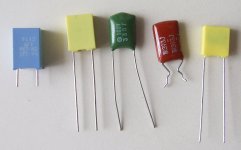
When you find so many amplifier boards using ceramic SMD capacitors for almost anything it is because they are cheap and can be mounted by robots. Not because they are necessarily the best choice. They can be difficult to replace because ceramic SMD capacitors are much smaller than foil capacitors. Chris, Voltwide, “doctormord” and other have done a huge job in the TPA325X threads of evaluating the different passive componenets.
My simple logic is as follows:
Most audio signal capacitors handle low power (input coupling capacitors, capacitors in the feedback, gain setting capacitors, filter capacitors etc….). Such capacitors are exposed to low currents such that ripple-sustainability is not an issue as long as the voltage rating and eventually polarity is correct. We want to avoid non-linearity in the capacitance, piezo-electric effects (a microphone effect picking up mechanical vibrations) and other noise. For such, normal foil capacitors (polypropylene, polyethylene or polyester) are considerably better than ceramic capacitors. You can find particular audio foil capacitors with huge size and considerable cost that are no-doubt the best but only matches the most demanding projects.
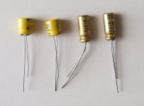
Sometimes you need signal capacitors that exceed 1-2.2uF in size at which point the foil capacitors become bulky. The traditional choice is electrolytic capacitors. Here you can get (statedly) better audio grade electrolytic capacitors, either polarized (as normal) or bipolar (without polarity if the voltage polarity may change). A very skilled forum member has stated that he has noticed no important differences between “normal” and audio grade capacitors (the manufacturers won't be happy) – I'm not the right person to judge.
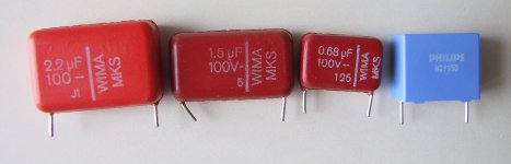
Class D output filter capacitors live a particularly unpleasant life with not only the audio signal but also ripple from the high frequency carrier signal (300KHz-1MHz). Here you need to consider the ripple-sustainability and ESR (low). The TPA325X guys and girls know more than I. I use some rather bulky Wima foil capacitors I have from the past (or, more smaller signal foil capacitors in parallel). The Wima seem to take the current “beating” well. Unfortunately, Wima capacitors are not cheap as they are high quality.
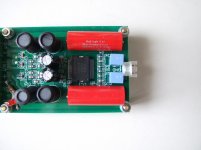
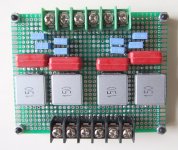
It is often very difficult to replace small initial output filter capacitors with (much) larger Wima foil capacitors. In such case, I often move the output filter to a separate board next to the amplifier board. With short leads and a good wire diameter, in particular for the GND-wire, I observe no detrimental effects. The advantage is I can move the filter to other amplifier constructions.
Class D power line decoupling capacitors have a rather steady DC voltage across them. Their main quality is low impedance to varying current demands, thus current ripple and low ESR (Equivalent Series Resistance). Here, I use low ESR capacitors. Often the dark green / golden Nichicon type, which are fair in price. The TPA325X people know much better. You can put smaller foil (or even ceramic) capacitors in parallel with the electrolytic power line decoupling capacitors to lower the ESR further. Or, you can use more smaller electrolytic power line decoupling capacitors in parallel but then you have to be carefull with your PCB layout if you want the more capacitors to share the ripple current well. Power line decoupling capacitors of correct size and quality are important because they supply the dynamic energy for the amplifier until the power source reacts.
One quick advice – if it is very diffucult to replace a ceramic SMD capacitor located in a place with poor access, you better leave it as it is. If you try to replace it, you risk damaging the PCB tracks and pads and then you really have a problem.
Also, do modifications that are cost-balanced compared to the value of the componenets you initially have on the board. Using very expensive capacitors and filter-chokes for a simple and cheap board hardly leaves any miracle.
Attachments
@FauxFrench: Wow! I'm deeply impressed with your idea to "move the output filter to a separate board". I never think about it and I will give it a try. It's might be a good idea for the audio DIYers.
I also appreciate your sharing of knowledge about capacitors, but sometimes it's hard to find the correct type of capacitor as expected in my location. Now I find my TDA7498 board is lack of bass and a bit harsh at treble then I will try to replace the output inductors and capacitors. Maybe it's not a miracle but as the DIYers, we will keep try and try and try... right? 🙂
I also appreciate your sharing of knowledge about capacitors, but sometimes it's hard to find the correct type of capacitor as expected in my location. Now I find my TDA7498 board is lack of bass and a bit harsh at treble then I will try to replace the output inductors and capacitors. Maybe it's not a miracle but as the DIYers, we will keep try and try and try... right? 🙂
- Status
- Not open for further replies.
- Home
- Amplifiers
- Class D
- Ebay cheap TDA7498 boards