I just orderd the amp and tonecontrol. Do you know any good cables to hook them up to eachother?
I don't really know some good cables. Maybe someone can chime in. I did read that it was a good combo. Sorry for going off-topic. Looks like the 7498 should be here tomm. I hope...

It's here! Yippee, Hooray, etc. this thing sounds incredible! Dialed in 12 o' clock WHOA LOUD! Boost 1 and 2 is nice and to my ears really brings out the music. I can't believe this thing is only 11 bucks.Will post some pics this weekend. Thanks guys easp, Mark and the others for your advice it worked out well. 😀 😀 😀
Thanks easp! 😀
TDA7498 100W+100W 2-channel Stereo Digital Power Amplifier Board From Ebay China(Seller tomtop_shop) Bought a 24V 5A adapter($15-20) as well:


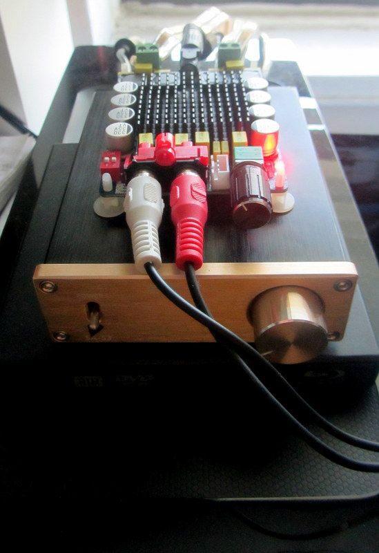
Came upon this amp after helping someone on the forums pick out a cheap amp. Saw this on ebay and did some research on youtube and diyaudio forum and settled on this one for $11.71 shipped from China! I said what the a fun project. 🙂 To my surprise it's quite a capable amp and louder than my SMSL SA-S3. Dialed in 12 o' clock WHOA LOUD! Boost 1 and 2 is nice and to my ears really brings out the music. 🙂 I can't believe this thing is only 11 bucks.😱Highly recommend getting one. The seller includes the feet, which I have not seen from others sellers and his is the cheapest too. 😀 If you buy this from a brand name with case it will cost over $100 for sure.
TDA7498 100W+100W 2-channel Stereo Digital Power Amplifier Board From Ebay China(Seller tomtop_shop) Bought a 24V 5A adapter($15-20) as well:


Came upon this amp after helping someone on the forums pick out a cheap amp. Saw this on ebay and did some research on youtube and diyaudio forum and settled on this one for $11.71 shipped from China! I said what the a fun project. 🙂 To my surprise it's quite a capable amp and louder than my SMSL SA-S3. Dialed in 12 o' clock WHOA LOUD! Boost 1 and 2 is nice and to my ears really brings out the music. 🙂 I can't believe this thing is only 11 bucks.😱Highly recommend getting one. The seller includes the feet, which I have not seen from others sellers and his is the cheapest too. 😀 If you buy this from a brand name with case it will cost over $100 for sure.
Yes, this amp sounds great.
But i like the lower gain more.
A nice feature of the amp is that can change the gain while listening to music.
That allows for a better comparison than soldering some resistors and then listen again.
But i like the lower gain more.
A nice feature of the amp is that can change the gain while listening to music.
That allows for a better comparison than soldering some resistors and then listen again.
Afterlife2 -- new amp board
Afterlife2,
Good! Glad it arrived intact and is working fine. Maybe I'll just try this version of the 7498 too. I love the version of the amp I bought, and think it's one of the best amps I have actually.
The particular version you have is nice because one can dial in various gain settings easily.
On my version, I haven't even found the need to run it with my Pass B1 buffer "preamp" or my tube buffer (6N3 based so called "Guanzo" or "Sain Smart"). It sounds great to me just running on its own using the onboard volume pot. Some of the other chip/class D amp I've experimented with seem to benefit from being mated with either one of those two buffer preamps. But none seem to need the extra gain of a conventional (active) preamplifier.
Interesting stuff. And certainly cheap enough to experiment with.
Enjoy!
--Mark
Thanks Mark you will love it. Which version do you have? Buehgemeiste I can actually do with the boost off, but it's cool it's there for such a cheap amp. I'm just so surprised on the quality and sound. Is it normal for it to spark a bit when plugged in? Almost forgot to ask what is the 3 pin white insert for on my amp? It's next to the volume control.
Afterlife2,
Unless I'm corrected by someone more knowledgeable, the white, 3 pin connector is an additional method of connecting your inputs (phone, CD player, FM tuner, etc.). You are using the RCA jacks, which is fine, but if you wanted to say, put this amp in an enclosure and have the RCAs on the back instead; then you would use an appropriate wire to make that connection from the white, 3 pin "header" connection to the back side.
I buy them on eBay. They have different spacings. All the amps I run use something like this.
10pcs Dupont Wire Cable 3P 3P Pin 20cm Header 2 54mm Pitch | eBay
For future readers (in case the link stops working) they are 2.54mm pitch, header wire, 3 pin. I cut one end off and wire to my own RCAs mounted on the back of my enclosures.
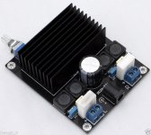
My amp is this one from ST Microelectronics in the attachment.
--Mark
Unless I'm corrected by someone more knowledgeable, the white, 3 pin connector is an additional method of connecting your inputs (phone, CD player, FM tuner, etc.). You are using the RCA jacks, which is fine, but if you wanted to say, put this amp in an enclosure and have the RCAs on the back instead; then you would use an appropriate wire to make that connection from the white, 3 pin "header" connection to the back side.
I buy them on eBay. They have different spacings. All the amps I run use something like this.
10pcs Dupont Wire Cable 3P 3P Pin 20cm Header 2 54mm Pitch | eBay
For future readers (in case the link stops working) they are 2.54mm pitch, header wire, 3 pin. I cut one end off and wire to my own RCAs mounted on the back of my enclosures.
My amp is this one from ST Microelectronics in the attachment.
--Mark
Attachments
Afterlife2,
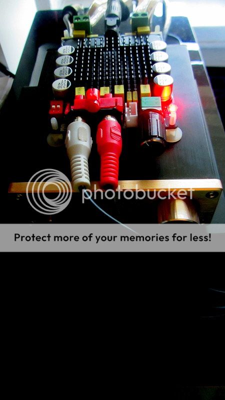
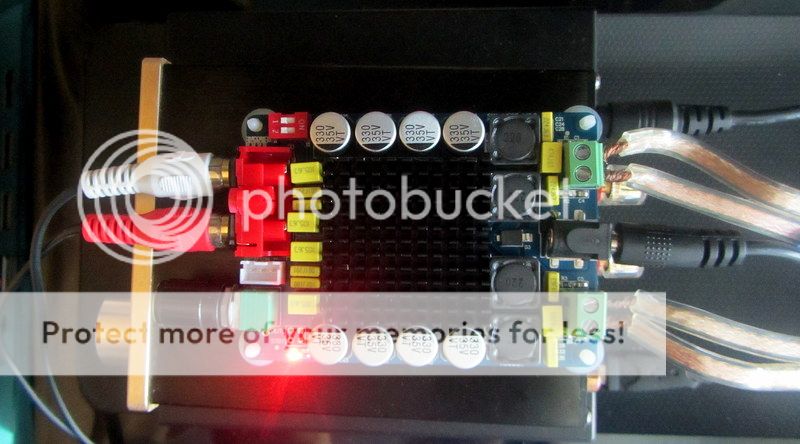
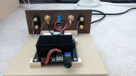
Some photos.
You can see the header wire connected to the white jack on the board, then it runs under the board and connects to the RCAs on the back side of this temporary mounting board.
Oh, about the spark. I'm guessing you are not using a switch and just plugging in the DC wire to the board. Yes, sometimes you get a spark when you do that. Not the ideal thing, but if you wanted to be safer, wire up a switch, or use a power strip with a switch on it to turn the thing on and off.
Mark
Attachments
Last edited:
Thanks for the info! Mark how about some pics of your actual setup? 😀 Whoa just as I typed this you posted. 🙂
Very nice Mark! What speakers and what's it connected to the PC? I need to make a box for mine. Great work there. Yeah I'm on a power strip I may do that to turn it off. Wired on/off switch where can I get it and where do I connect it?
Last edited:
Send me a P.M.
Hey Afterlife2,
If so inclined, send me a private message and I'll pass along my number. Might be easier and faster to discuss stuff one on one. I can help you out with a lot of basic stuff that took me awhile on my own to get figured out.
Even wiring up an on/off switch was a challenge to me at first!
It's all easy if you know how. But not all of us do. And I think we beginners just bore the other guys on the forums.
I'd be happy to help you. I'm not an expert but I'm happy to help out.
Mark
Very nice Mark! What speakers and what's it connected to the PC? I need to make a box for mine. Great work there. Yeah I'm on a power strip I may do that to turn it off. Wired on/off switch where can I get it and where do I connect it?
Hey Afterlife2,
If so inclined, send me a private message and I'll pass along my number. Might be easier and faster to discuss stuff one on one. I can help you out with a lot of basic stuff that took me awhile on my own to get figured out.
Even wiring up an on/off switch was a challenge to me at first!
It's all easy if you know how. But not all of us do. And I think we beginners just bore the other guys on the forums.
I'd be happy to help you. I'm not an expert but I'm happy to help out.
Mark
@Mark2727 There has been some talk about some bizzare design choices on the board you have, namely the resistors on the output. I think someone tried shorting past them and found that it worked well. You might want to search within this thread for more details.
@Afterlife. Glad your new board is working well for you. This might be a good time to clip the ends off your speaker cables and restrip them to get clean copper and reduce the chance of a stray strand shorting a channel.
For RCA panel connections via the JST connector, there is also this adapter board + cable, along with similar boards that also include a switched 3.5mm jack.
Thanks easp,
Hmmm...didn't know that about the board I have. So, not sure what you mean by "shorting past them".
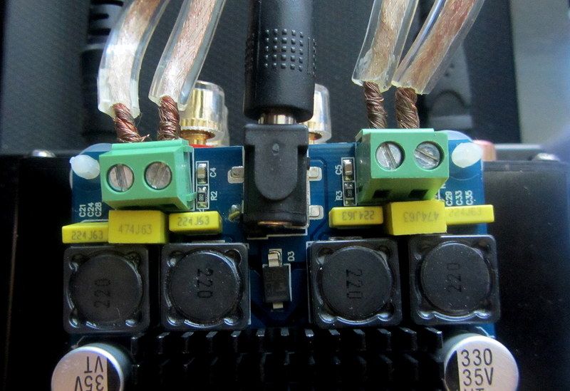
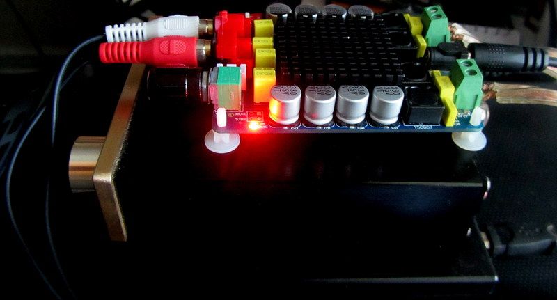
Do you mean I should somehow bypass those 5W 2.2 ohm white resistors near the screw terminals for the speakers?
I'd need a good explanation or a sketch or photo probably to inplement that fix. But I'd sure be willing to try it. Don't know how I missed that on this thread, but I'll check it out.
If anyone has knowledge of this and how to help me, please chime in.
Thanks,
Mark
Hmmm...didn't know that about the board I have. So, not sure what you mean by "shorting past them".
Do you mean I should somehow bypass those 5W 2.2 ohm white resistors near the screw terminals for the speakers?
I'd need a good explanation or a sketch or photo probably to inplement that fix. But I'd sure be willing to try it. Don't know how I missed that on this thread, but I'll check it out.
If anyone has knowledge of this and how to help me, please chime in.
Thanks,
Mark
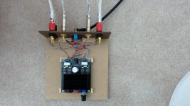
I'm reading posts #46 and 47 on page 5 here just now about my amp (see photo below).
Is that true that the right channel speaker screw terminals are marked wrong?
If so, my understanding is that each negative speaker lead would be towards the inside of the amp board, and each positive speaker lead would correctly be oriented towards the outside of the amp board.
Have I got that correct?
Thanks,
Mark
Attachments

Thanks easp,
Hmmm...didn't know that about the board I have. So, not sure what you mean by "shorting past them".
Do you mean I should somehow bypass those 5W 2.2 ohm white resistors near the screw terminals for the speakers?
I'd need a good explanation or a sketch or photo probably to inplement that fix. But I'd sure be willing to try it. Don't know how I missed that on this thread, but I'll check it out.
I stumbled across some of the posts discussing the mod while looking for something else. Check post #88 and #89 in this thread.
Thanks easp,
I did it (easy)and am listening to it now. Yes, the posts at #89 & #89 are extremely helpful.
I also got the speaker lead out wires in their correct positions per posts #46 & #47 on page 5.
Thanks to everyone! I'm not knowledgeable enough to review schematics/boards for mistakes like this. I'm very appreciative of those who do and help out!
Mark
Thanks easp Whoa look at all this great info! I switched my speaker wires now I get a bit more BASS. Was wondering why I had to put the boost on, although it does fill in the low end more. Mark I might get this: T2R5 Wht Wireless AC Power Wall Outlet Socket Remote Control on Off Switches New | eBay
Thoughts?
Thoughts?
- Status
- Not open for further replies.
- Home
- Amplifiers
- Class D
- Ebay cheap TDA7498 boards