The imbalance would only appear after 5-10 min or so with the volume getting lower right channel.
I assumed it was a bad joint sensitive to temperature.
So I redit all suspicious solder joints on the right side.
It is now fixed and balanced.
I assumed it was a bad joint sensitive to temperature.
So I redit all suspicious solder joints on the right side.
It is now fixed and balanced.
 Congratulations
Presumably 1A sluggish at 230V will be enough.
For 120V 3.15A is recommended.
What is the power of the transformer?
For 120V 3.15A is recommended.
What is the power of the transformer?
Make that 175W. The 36W is the amp output.
Mona
Thanks Mona,
The info on the web site is misleading.
I thought that value was not right judging by the iron weight 🤔!
The info on the web site is misleading.
I thought that value was not right judging by the iron weight 🤔!
The highest current will flow when switching on. If 1A6 is not enough, 2A would be the upper limit.
Unfortunately, I have no experience with the tubes when it comes to heating when switched on. The experts will definitely report back here.
Unfortunately, I have no experience with the tubes when it comes to heating when switched on. The experts will definitely report back here.
In my older designs I used an 8A fast blow fuse... Now I use a 3A slo-blo.
For the SPP at 230V, I'd say 3A fast acting or 1A slo blo. if 1A isn't large enough go to 1A5.
The only thing that will blow the fuse besides a fault is the initial surge current on turn on, and where it is in the waveform when you hit the switch.
For the SPP at 230V, I'd say 3A fast acting or 1A slo blo. if 1A isn't large enough go to 1A5.
The only thing that will blow the fuse besides a fault is the initial surge current on turn on, and where it is in the waveform when you hit the switch.
Double protection:
1. A Fast Blow Fuse in the power transformer primary for the inrush current of a cold amplifier at power up.
Example: Cold filaments (1/4 of hot resistance, 4 times the current at turn on), and if the B+ uses solid state rectifiers, the charging of the filter cap is very quick - a large turn on transient current.
And . . .
2. A Slow Blow Fuse in the power transformer primary so that if a warmed up amplifier has a fault . . .
An output tube that has thermal run-away current; an output tube that has the screen get hot and deform badly, so that it touches the control grid (short).
All my amplifiers have the power transformer primary fast blow and slow blow double protection:
One of my amplifiers has a 1.5 Amp fast blow fuse for the inrush, and a 0.5 Amp slow blow fuse in case of an output tube fault.
Your fast blow fuse and slow blow fuse ratings will vary (measure the maximum inrush current; several times; it happens on a cold amplifier, when the power switch comes on at the crest of the sine wave).
Or
Start with a small value fast blow, if after a few cold start ups, it blows, then use the next higher current rating.
Then, after finding the correct fast blow fuse, put in a small value slow blow in series. If it blows, then try the next higher current rating, etc.
One amplifier I had would power up and run for many hours; it had a 0.5 Amp slow blow fuse; but after a few weeks the slow blow fatigued and opened up. A 600 mA fuse now always works (0.6 Amps, just a litter hard to find a source for one). It never blows now.
Just my opinion.
One amp I built would power up and run 99 times in 100 using a 2.5A fuse... That 1 time though was where the power cycle causes maximum inrush and it would pop. 3A and it's been fine.
Hello,
I have a pcb based on a wiring diagram of the audio research VT60 SE, in the list of components are indicated RIKEN 2watt resistors - 4 x 200ohm, 4 x 10ohm and 1 x 1ohm, it is specified that they must be selected with a minimum deviation from the indicated value. Unfortunately they are almost impossible to find.
I bought vishay dale 2watt 200ohm 1% tolerance (CPF2200R00FKB14) - dale 2watt 10ohm 0.1% tolerance (CPF210R000BHE14) and dale 2watt 1ohm 0.5% tolerance (CPF21R0000DKB14).
I think there should be no problems with the operation, but I would like a guru's opinion.
I would like to thank in advance those who do their best to answer my question.
attach wiring diagram
Attachments
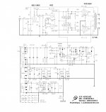
Well they are exagerating, not only precision, but also al those parallel resistors 🤣
5% is close enough exept for R24-25. If you want exact reading of the bias current use 1%.
With all those resistors the importent ones are missing 😒
If a bias potmeter fails the tube has no negative grid voltage no more, not very healty.
To prevent a catastrophy put in 4 resistors.
Mona
5% is close enough exept for R24-25. If you want exact reading of the bias current use 1%.
With all those resistors the importent ones are missing 😒
If a bias potmeter fails the tube has no negative grid voltage no more, not very healty.
To prevent a catastrophy put in 4 resistors.
Mona
Attachments


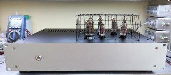
I love that open frame wire cover!
Have fun listening, and have fun watching the fruits of your labor.
Have fun listening, and have fun watching the fruits of your labor.
Those chickens lay any eggs yet? 😉
Congratulations on your build. It's a good feeling of accomplishment to build something with your own hands.
S.
Congratulations on your build. It's a good feeling of accomplishment to build something with your own hands.
S.
- Home
- Amplifiers
- Tubes / Valves
- Easy DIY tube amp