Icsaszar's advise is sound. Check to see if it hums on it own without input. I suspect it will....
If you have an appropriate 'app' on your phone, you will be able to see if the hum is 50Hz or 100Hz (or both). This helps direct where the source of the hum is.
Also, if you can simply un-hook the step-up transformers it would also be useful.
Ian
If you have an appropriate 'app' on your phone, you will be able to see if the hum is 50Hz or 100Hz (or both). This helps direct where the source of the hum is.
Also, if you can simply un-hook the step-up transformers it would also be useful.
Ian
Yeah. grid stoppers are a must-do for phono. Many years ago, when I built my first version of this circuit, I used little hammond chokes on the DC heater supply. But there was a small 50Hz hum. I knew this hum was not from the B+ supply as it was well regulated. So I built a simple DC circuit using LM317. No more hum. Glorious sound. 🙂Aha. There aren't any grid stoppers 🙁
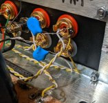
The thin aluminium shield between the PSU and the input wiring that I see in the pictures won't do anything. Everything looks to be mounted on the same aluminum plate, so if there is any Mains or Choke vibration it will be heard.
Ian
Looking at the picture, rotating the mains transformer 90 degrees is another thing that can be tried.
also, I see a switch to go from step-up transformer input to MM input. I would remove that too while trouble-shooting. Switches on phono input are always bad news. especially if they are not fully shielded.
I have measured it earlier. It mainly 50hz trough the SUTs, but there is also a 100hz peak. I did some tube swapping earlier and with one set of tubes the 100hz became just as loud as 50hz, especially if I cracked up the volume.Icsaszar's advise is sound. Check to see if it hums on it own without input. I suspect it will....
If you have an appropriate 'app' on your phone, you will be able to see if the hum is 50Hz or 100Hz (or both). This helps direct where the source of the hum is.
Also, if you can simply un-hook the step-up transformers it would also be useful.
Ian
I did not unhook the SUT but since I run both + and - trough the switch they should not come trough when switched to MM.
If I ground the switch and use the JJ ECC83S tubes, amp is pretty much silent with nothing at all connected to the inputs. . Hiss and white noise if I crank up the volume. If I use my Brimar CV4004 the first tube pics up hum, more so if I touch it. With the JJ ECC83S this is not a problem. But with shorting plugs into the MM inputs I get a some 100 hz hum.
Since the switch is attached to woo it does not touch the metal chassis and hum is reduced a bit if I run a wire from switch and ground it to chassis. I will do it permanently later if I do not need to redo the entire enclosure to get a better shielded one.What exactly is meant by "ground the switch"?
Hi
Good to know you are finding ways to get rid of the hum.
Sorry to tell you this, but switches on phono input are always a bad idea (imho). Your switch is not shielded, and it will be hard to shield. It works like an antenna as it is right now too. Do you get any RF signals? Hope no cell phone towers are nearby. 🙂
The step-ups are right beside your input tubes as well. And your tubes are not shielded. Place shields on the tubes and ground the shields if you can do this. Then you might not find the need to swap different tubes, etc.
Try this for now: Wire the MM inputs directly to the input of the board. Then use an MM pickup. Make sure there are no ground loops with the turntable ground and tonearm ground. The tonearm ground wire should go to your ground post on your Phono amp.
Ian
I would put the step-up transformers in a separate fully shielded metal box. This allows you to place them somewhere else, where they will not induce hum. Yes, you will need extra cables for this. Sorry.
Also, the metal box for the step-ups will need to be grounded too. Best is to put all grounds to the ground post of your phono amp.
Also, the metal box for the step-ups will need to be grounded too. Best is to put all grounds to the ground post of your phono amp.
Ah I see your phono amp has no ground post. Every decent phono amp needs a ground post. Where else can you ground your tonearm cable to?
I think your wood box looks very nice, but there is a reason the best phono amps are in a fully enclosed metal box...
It's easy to underestimate the amount of shielding needed in phono circuits, especially at the tiny signal end. Rega hasn't done you any favors either.Since the switch is attached to woo it does not touch the metal chassis and hum is reduced a bit if I run a wire from switch and ground it to chassis. I will do it permanently later if I do not need to redo the entire enclosure to get a better shielded one.
All good fortune,
Chris

Many years ago I tried to do things like this. Then I decided it was simply foolish. Input switches for such small signals make input switches a bad compromise.Since the switch is attached to woo it does not touch the metal chassis and hum is reduced a bit if I run a wire from switch and ground it to chassis. I will do it permanently later if I do not need to redo the entire enclosure to get a better shielded one.
There are a LOT of reasons why this is the case. Besides the increased hum, you also add a whole lot of capacitance to your input.
My solution? Build a SECOND phono amp! 🙂 I also designed it differently. Great project. Highly recommended.
In the picture of your phono ( 1st post ) output signal wiring goes right over the high voltage and heater cables. High voltage cables can couple hum if close to output signal wiring - change the routing to the right side of the pcb if you can.
This is from my experience with phono preamps.
This is from my experience with phono preamps.
@AweLoi - lots of advice here, and I think it might be hard to figure out what to do first.
So, I'd suggest you have a couple of different things to tackle:
1. hum/buzz from grounding or power supply. The way to get an idea where this noise is coming from is to short the input jacks (short signal + to signal ground) - commonly done using shorting plugs. This tells you what is the noise from the unit itself - you can differentiate between noise from outside and noise from inside. If you have a pair of cheap interconnects from an old DVD player etc, you can make a handy set by cutting off the plugs at one end, stripping both wires and soldering them together. It is also useful when tracking this sort of thing down to simplify everything as much as possible, so if you have noise from within the unit, it is good advice to disconnect the stepup transformers first, sort out the noise, then add them back in, and sort out whatever additional problems they might or might not add.
2. RF interference - try the capacitors to chassis earth as I suggested. Other advice is to use a metal case, shield the tubes etc... but if you take that one step at a time then you at least know you are on the right track. With the capacitors in place, attach a set of cheap interconnects to the input, with the other end just in the air, and see if the RF is gone. The interconnects act like an antenna and will tell you how well the RF rejection is working.
3. Then sort out your tonearm issues - from your description it does sound like you have a break in the wire somewhere from cartridge tag to phono plug. If you are lucky, this will just be a wire break you can fix inside the tonearm connector which you can open at the bottom of the tonearm post. without fixing this, you will have noise once you plug (the broken) tonearm in - and you will also have noise without the cartridge connected.
Lastly - you tested the continuity with a multimeter with the cartridge still in place. Some older multimeters used quite a high voltage for continuity/resistance tests, and could damage a cartridge. This is much less likely with more modern multimeters, I hope you got away with it.
I have installed a ground post since that picture. I just hadn't received it yet when the picture was taken, and I was in no hurry since Rega run the tonearm ground trough Left shield.Ah I see your phono amp has no ground post. Every decent phono amp needs a ground post. Where else can you ground your tonearm cable to?
I have gotten a lot of tips now.
Fist of all, my TT interconnect do have a broken wire. I have tested it now and will have it replaced.
Secondly I put the SUTs within this build for pure convenience but if it creates hum I will will put them in a separate enclosure as my first step and remove the switch. I do not own a MM cartridge but I can run this cartridge without a SUT and at least get sound and see if hum is present without SUTs.
If I still have hum after this I might have to build a new enclosure, better shielded, perhaps even a two box solution with PSU in it's own enclosure.
Hopefully I can keep this build since I really liked how it turned out esthetically, but hum free sound is more important. 🙂
I have already implemented the circuit that you see in this grounding scheme below. X2 cap and 10 Ohm resistor (bottom of picture). Would that be the same thing as what you are suggesting? It made no difference though.2. RF interference - try the capacitors to chassis earth as I suggested. Other advice is to use a metal case, shield the tubes etc... but if you take that one step at a time then you at least know you are on the right track. With the capacitors in place, attach a set of cheap interconnects to the input, with the other end just in the air, and see if the RF is gone. The interconnects act like an antenna and will tell you how well the RF rejection is working.
No, not the same thing.... what you have there is a ground loop breaker (which is a good thing and you should keep it).
One end of each ~10nF cap goes to the ground of the input RCA socket. The other ends join together and go to chassis/mains earth.
So if you look at the photo, you'll see one with 2 ceramic 10nF caps, one end of each at the RCA ground, and the other ends go to chassis ground (out of shot).
If you can, make the leads shorter than in this photo.....
Attachments
Ok, thanks! I do not have those caps at home so in that case need to place an order. I'll start with bypassing SUT and switch and see if that might be enough: After that I'll order the caps and some copper tape for extra shielding and see if that is enough. 🙂One end of each ~10nF cap goes to the ground of the input RCA socket. The other ends join together and go to chassis/mains earth.
I have now finally been able to remove some of the hum thanks to the help from you fine guys. I had to take some time off from this project since it drained my energy and then started with changing the cable on my turntable so that it was functioning properly again. I then ordered some Mogami 2497 cable that I am going to use as interconnects but I ordered some extra to use as internal cables as well since the ones I previously used where not shielded, because this was a shielding issue as some of you suspected.
I then inserted an extra aluminum wall between the PSU and main board. Honestly it is probably not needed but why not?. I then inserted an aluminum piece on the back wall, since this was left unshielded and this made a significant difference.
I then bypassed the SUT and the switch and worked from there with shorting plugs. I tried to ground the metal casings of my RCA jacks to chassis, as one you mentioned, and surely, hum was reduced even further. They acted as antennas when only touching wood. At this point the hum is acceptable but if I turn up the volume to loud listening levels it is still to loud for me to be content. I do think I need to build a new enclosure to get it perfect so I will leave it as it is for now.
Then I reinserted the switch. A tiny bit more hum, but acceptable in regards to the convenience it gives. It too is now grounded to chassis.
Next I reinserted the SUT but now with an extra aluminum case around it. Did not add any hum. Phew! And with SUT wired to 1:16 gain I can reduce volume on my preamp and hence lower the noise floor from the phono stage some more. It's not dead silent but way better than is was.
I think I will try the 10nf caps thing too but will wait until I need to order some more stuff from Mouser. Shipping is too high for just a couple of caps.
- Home
- Amplifiers
- Tubes / Valves
- EAR834p clone with hum. Would appreciate some help