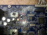
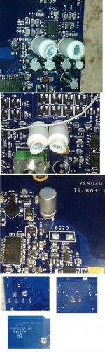
See pre-adc power caps on attached pic 'Resize of Photo-0078x.jpg'. They're for all input opamps power. One positive supply another one - negative. And zero-ohm resistors that connects this opamps group + this caps to 'global' power wires are near to that caps. In post 140 I didn't replace them with polymer caps, only added polymer ceramic. But I replaced them with polymer caps too in post 144. Photos with all power caps replaced is another attached pic: 'caps_replacement.jpg'. Note that there'is still empty placeholder named C259 - after taking that photo I soldered there another polymer cap as DC converter datasheet requires, but this didn't change anything significally.
About builtin headphone amp - I didn't care about it cuz I'm using external one.
About builtin headphone amp - I didn't care about it cuz I'm using external one.
Attachments
Last edited:
"only added polymer ceramic" => "only added ceramic".
However one more thing about builtin headphone preamp. Those two 220uF caps that powers its output opamp are not bad. I measured their ESR - quite good caps, no strict need to replace them, unlike other caps that I replaced.
However one more thing about builtin headphone preamp. Those two 220uF caps that powers its output opamp are not bad. I measured their ESR - quite good caps, no strict need to replace them, unlike other caps that I replaced.
DAC and ADC mods?
Wow, great stuff! Thanks a lot Misterzu for posting all these nice measurements and A-B comparisons of your mods.
Timing is perfect for me as I just started up my E-MU for the 1st time (it has been laying on a shelf since I bought it over 3 years ago). It will be used as DAC and to digitize my old LP records collection. So my only concern is audio quality.
I am positively surprised by the sound quality out of the box, using a dedicated 5V analog PSU. It comes very close to my heavily modded Sony CDP X33-ES. But mods are planned, first of all to use a pair of output transformers post-DAC.
I have a few questions on your mods:
Sorry for all my questions, this is for my understanding, before ordering parts. Thanks 1E6!
Nijs
Wow, great stuff! Thanks a lot Misterzu for posting all these nice measurements and A-B comparisons of your mods.
Timing is perfect for me as I just started up my E-MU for the 1st time (it has been laying on a shelf since I bought it over 3 years ago). It will be used as DAC and to digitize my old LP records collection. So my only concern is audio quality.
I am positively surprised by the sound quality out of the box, using a dedicated 5V analog PSU. It comes very close to my heavily modded Sony CDP X33-ES. But mods are planned, first of all to use a pair of output transformers post-DAC.
I have a few questions on your mods:
- Why did you go up so much in value with the electrolytics, as the AKM datasheet suggests 10uF //0.1u close to the DAC and ADC?
- Did you consider any more bypassing close to the ICs?
- Any mods to the DAC and ADC sections?
- The other day, I came across this thread about low-quality ceramic capacitors in cheap Behringer 2496 systems. Any chance we could expect improvements from replacing these parts in our EMU systems?
Very interested in opinions here!
Sorry for all my questions, this is for my understanding, before ordering parts. Thanks 1E6!
Nijs
I used that capacity value because thats only polymer caps with suitable voltage that were on my shelf 🙂 I was a bit afraid that too big capacity can cause PWM instability - but everything works fine - I didn't notice any instability manifestations since made that mod.
And why I'm using polymer caps - because of their good characteristics to on high frequencies. EMU on-board PWMs work at 160KHz, but 160KHz - is a frequency of very short pulses, so actual spectrum of that pulses IMHO reaches to tens of MHz, so really good caps required to filter them and SMD inductors also useful on such frequencies, and also there'is so suitable place for them - dummy 0Rs🙂.
And that PWM's pulses observable almost everywhere on board - on opamps power pins, on outputs, and due to tricky board ground pathes - even between grounds of outputs and inputs. DAC/ADC powered from linear regulator and oscillograms of their power lines looks rather smooth and also on DAC's output only white noise observable, without visible pulses.
Question for the hard core e-mu 0404 modders - would it be possible to dig in an AK5394A instead of the AK5385A? Same package but different signals. After 5 minutes I'm not clear of how to interpret the newer names of the pins to the old ones. Maybe even they aren't compatible giving that some of the old pin signals might be handled internally freeing pins for totally different signals...
On the dac side the newest dac is in a totally new package with 44 pins of which 32 are used and maybe a few pins could share the same gnd... (hopefully), is there somekind of adapter so one could put an AK4397 in place of the AK4396. Surely a lot of whys, hows and again hopefully some recommendations especially on how and possible gains of even thinking about it 🙂
Regards
Misterzu, thanks for clarifying. Reasons for selecting polymer caps are obvious, I will probably go for slightly lower values closer to original.
I have another question. In the schematics you posted earlier, values of many capacitances and also several resistors have been changed. Can you comment on why, and if this gave any improvement? You used c0g ceramics IIUC. For caps in the signal path in discrete audio, I tend to use film caps with good sonical results. Would that be recommended here, for instance for C1, 2, 101?
Also it looks like you bypassed the input caps on the high Z inputs and made several other mods to the original design.
@ Turbon: I have no experience in such drastic upgrades, but can not see any reason why you would try such a mod on this device, even if it were theoretically possible. Potential gains will be minor (if any) and risk of failure is immense. It might be more useful to start with a newer cheap high performance DAC from our Chinese friends and mod that.
Just my opinion of course... 😉
Has anyone tried bypassing the input caps? That's how it is in the 4396 manual...
Hi, I think the caps are only needed in case you are using the 48V phantom power. Mods to the input circuitry are discussed here, see post 64:
http://www.diyaudio.com/forums/equi...tifacts-peaks-left-channel-7.html#post4175441
Plus schematics by Sidiy. By the way, the Wiki seems to have disappeared. Anybody knows what happened? 😕
Hi,
Output op are +-6v...I made custom psu and set +-6v...any benefit to raise V i`m "hobby" electronics...etc
Output op are +-6v...I made custom psu and set +-6v...any benefit to raise V i`m "hobby" electronics...etc
Hello
Anybody would have the the schematic of the power supply and line input circuit for the E-MU 0202 USB (Creative), model EM8740 ?
Thank
Bye
Gaetan
Anybody would have the the schematic of the power supply and line input circuit for the E-MU 0202 USB (Creative), model EM8740 ?
Thank
Bye
Gaetan
Hi, I think the caps are only needed in case you are using the 48V phantom power.
Are they needed if I use a standalone 48V phantom power box?
v
Are they needed if I use a standalone 48V phantom power box?
v
If there is a DC component in your input signal you need blocking caps.
To avoid any risk of toasting your ADC input buffer I would keep the input caps, unless you are absolutely sure your signal will never contain any DC offset.
Replace the electrolytic caps with good quality ones (rated at 63V) and I doubt anyone will hear a difference. Even better to use bipolar ones if available, or 100uF back-to-back, if you can make them fit.
I realized that I asked about the wrong thing. By input caps I meant the capacitors that are at the output of the dac, C80 and C81 for the left channel. They are omitted on page 34-36 of the datasheet here http://www.akm.com/akm/en/file/datasheet/AK4396VF.pdf
My bad
My bad
Answering my own question after rereading the thread and wiki: decoupling caps can be bypassed but may output DC or not have enough voltage swing at high volume levels.
Now I have another one: what numbers are the TVS diodes for the headphone section? I see D25 is listed as the left channel but not sure since D1-3 are really D26-28
Now I have another one: what numbers are the TVS diodes for the headphone section? I see D25 is listed as the left channel but not sure since D1-3 are really D26-28
The TVS diodes are shown in the schematic here http://www.diyaudio.com/forums/digi...-mu-0404-usb-modification-10.html#post3473361
The true labels for the balanced and SE diodes are wrong on the schematic as noted above and in the thread. Left and right sides are D26-D31 and I will remove them.
The problem is: the headphone output diode is D25 on the schematic but not sure if that value is wrong as well and I am not sure what its right side equivalent label is.
There is an information about these diodes on emu 0404 wiki
http://www.diyaudio.com/forums/diyaudio-com-wiki/162512-e-mu-0404-usb-mod-wiki.html
http://www.nxp.com/documents/data_sheet/MMBZXAL_SER.pdf
http://www.vishay.com/docs/85622/1n914.pdf
Is that OK for you vladimirbob?
http://www.diyaudio.com/forums/diyaudio-com-wiki/162512-e-mu-0404-usb-mod-wiki.html
http://www.nxp.com/documents/data_sheet/MMBZXAL_SER.pdf
http://www.vishay.com/docs/85622/1n914.pdf
Is that OK for you vladimirbob?
I was just going to remove them and not replace with other diodes.
I am just not sure what item number they are on the silkscreen (D25, etc)
I am just not sure what item number they are on the silkscreen (D25, etc)
Unfortunately, I haven't this information.
And my emu is not open this period to look the type of diodes.
And my emu is not open this period to look the type of diodes.
So, are there any confirmed tweaks for our 0404 USB that yield audible improvements to the DAC as far as listening to music via the line out? I've scrolled through the thread see a couple mods that reduce the THD rate, but it's all way way below audible levels.
- Status
- Not open for further replies.
- Home
- Source & Line
- Digital Line Level
- E-MU 0404 USB Modification?