Next was the transformer, the original coating looked like it was Amber Shellac which was applied somewhat carelessly.
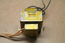
Testing the finish with a dab of denatured alcohol on a q-tip confirmed that it was indeed shellac (it got soft) so I removed it with lacquer thinner and a green scotch pad. I then applied a coat of clear lacquer with a brush
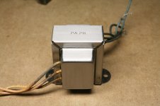

Testing the finish with a dab of denatured alcohol on a q-tip confirmed that it was indeed shellac (it got soft) so I removed it with lacquer thinner and a green scotch pad. I then applied a coat of clear lacquer with a brush

I want to keep this as original as possible.
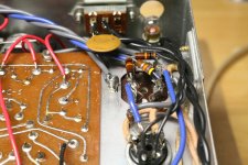
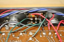
I would still replace the 1uF electrolytic coupling capacitors on the outputs, best to use 35V or 50V parts.
Last edited:
I would still replace the 1uF electrolytic coupling capacitors on the outputs, best to use 35V or 50V parts.
Are those attached to the bass pots?
Yes, they block DC voltage from the input cathode coming through the tone/feedback
network to the audio output. These were added when the "X" tone controls were included
as standard.
network to the audio output. These were added when the "X" tone controls were included
as standard.
Last edited:
Yes, I did order a pair of Nichicon 1mfd 50V caps. The Dynaco assembly manual refers to them (originals) as being polarized, these Nichicons are not, is that a problem?
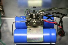
You can use it for everything, but you must use it from the quad cap to the line stage board (+330VDC, pcb eyelet #16),
and also from the quad cap to the rectifier tube socket (+405VDC, tube socket pin #7).
and also from the quad cap to the rectifier tube socket (+405VDC, tube socket pin #7).
Last edited:
You can use it for everything, but you must use it from the quad cap to the line stage board (+330VDC, pcb eyelet #16),
and also from the quad cap to the rectifier tube socket (+405VDC, tube socket pin #7).
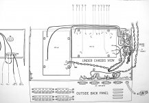
There is a wire that runs from lug #4 of the quad cap to eyelet 16 of PC-6. Should this also be 600V wire?
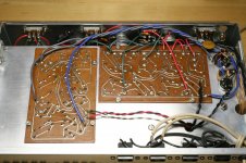
The pictorial shows that same wire routed past the tone controls, can it be run on the other side of the chassis between PC-5 and the wired AC outlets instead?
I would keep it as shown, close to the ground return wires from the phono board.
When I used to build these, I twisted the HV wires with the ground return wires
for each board.
When I used to build these, I twisted the HV wires with the ground return wires
for each board.
Last edited:
I would keep it as shown, close to the ground return wires from the phono board.
When I used to build these, I twisted the HV wires with the ground return wires
for each board.
Will do, thanks again.
To avoid hum issues my recommendation is to follow the manual exactly.There is a wire that runs from lug #4 of the quad cap to eyelet 16 of PC-6. Should this also be 600V wire?
The pictorial shows that same wire routed past the tone controls, can it be run on the other side of the chassis between PC-5 and the wired AC outlets instead?
Twisting B+ and ground is of limited value as they connects to the board far from each other.
To avoid hum issues my recommendation is to follow the manual exactly.
Twisting B+ and ground is of limited value as they connects to the board far from each other.
Thank you for the suggestion. I've already twisted them. It's a tidy setup so I'll leave them for now.
- Home
- Amplifiers
- Tubes / Valves
- Dynaco PAS 3X Re-Build
