Nordic said:....but I can start shipping the orders without the extra modules on Tuesday when the shops and post office reopens after the easter weekend.
Sorry for being so quiet this week, but I was realy pretty sick...
Nordic, hope you are rid of the bugs (flu) by now.
Re. shipping the Precision orders; speaking only for myself, delaying the Precision PCB shipment and shipping it a bit later with the protection module PCB would be fine -- still working on the HRII, and getting there slowly.
Best
Francois
stereodave said:Taj,
Are fuse types M205 or 3AG or can either be used?
Nico can correct me if I'm wrong, but by my measurements, the fuses are almost certainly the 5x20mm (M205?) type, not the .25" x 1.25" (3AG?) type.
..Todd
stereodave said:Taj,
Comments on the component layout:
There are two C3's, I think C5 100nF is mislabelled.
CIn is 4.7uF but the schematic of 29th Feb had it as 10uF electro, which is correct?
C33 68pF - Is this C13 on the schematic?
Are fuse types M205 or 3AG or can either be used?
I appreciate the effort you have put into this and I hope my comments help.
C5 label is fixed
C33 is changed to C13 to match published schematic (Nico's group-buy PCB silk screen will probably say C33 for this cap.)
C-In and fuses addressed earlier.
Latest drawing attached.
Attachments
 I say thank you again...
the bom has been posted, I suspect in the HRII thread, will look when I get up...
You would be surprised at how good a cheap non-polar electrolytic on the input can sound. Grab a handfull in a variety of values and see for yourself, they should only be a few cents each.
You would be surprised at how good a cheap non-polar electrolytic on the input can sound. Grab a handfull in a variety of values and see for yourself, they should only be a few cents each.
Signal GND
Hi Nordic,
Why did you connect -IN to the Power GND?
It is suppose to be connected to the Signal GND, and D1||D2||R5 linking SGND to PGND.
Thank you for your effort.
😎
Hi Nordic,
Why did you connect -IN to the Power GND?
It is suppose to be connected to the Signal GND, and D1||D2||R5 linking SGND to PGND.
Thank you for your effort.
😎
Why did you connect -IN to the Power GND?
I'm guessing that the reason might be, that since the length of the trace joining D1,D2 and R5( the potential signal ground) to the power ground is so very short , joining the signal ground trace a few millimetres closer to the trace junction of D1,D2,R5, might not make much difference.
Billabong.
You know Bob, you are on to something...
The original schematic did not show in-, so out of force of habit I connected it to gnd... and the prototype worked fine....
If however you are haveing GNDing problems, cut the trace going to the groundstar and wire a junction in from in- to the top leg of the 15k resistor a centimeter or so to the left.
I updated my personal files with it for future boards, many thanks...
Yes, if you do the mod as described above, you will get the same configuration as Bora's schematic...
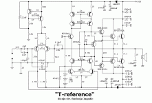
Parts layout questions
Thanks very much for your fine work on the latest parts layout in post #823, TAJ! A couple of questions re. layout, probably for Nico to answer.
1. Why are R28-33 shown below the board? Seems to me nothing would prevent one from mounting them above the board.
2) Same question for C23-25. Perhaps they would serve as a stop below the board when installing the board on the heat sink bracket, but that will be on one side only.
Thanks,
Francois
BOM location
The BOM posted in #580 of this (Precision) thread.
Francois
Nordic said:the bom has been posted, I suspect in the HRII thread, will look when I get up...
The BOM posted in #580 of this (Precision) thread.
Francois
In deed, it is totaly up to you... and my prefereance is also for mounting above board. Some poeple like a clean uncluttered look in fact I think Carlos asked me to depict the boards with them not showing, and they can opt to add them to the bottoms. There are a few components best placed at the bottom, but it will be pretty apparent when you build. I would say its an easier construction project than the HRII and original DX.
Also some people think that wire links are design errors... the same people who would use double sided boards with no worries.
The simple truth is that there is only so much you can do with a single sided design (for costs reasons), Now open up any commercial gear and start counting the links... tonnes. I was a little slow in takeing up wire links due to all kinds of rubbish theories... but part of my "training" is to open up as much gear as I can and look at construction techniques and copy best practices.
Thanks Francois...
Re: Parts layout questions
My pleasure. It's my only way of contributing until I learn more about electronics.
..Todd
Francois G said:Thanks very much for your fine work on the latest parts layout in post #823, TAJ!
My pleasure. It's my only way of contributing until I learn more about electronics.
..Todd
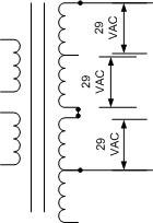
Precision I PS transformer question
(Hope this is OK to ask here)
I have a large toroidal power transformer (rated 1kVA) and would like some advice on "alternative" use of in my upcoming Precision project.
This transformer has 2 separate secondaries and both are center-tapped. Each secondary gives +41 0 -41 VDC on the two rails when loaded to draw ~8 amps (which I think should be more than average of the Precision for stereo channel requirements).
The question: Are there any pitfalls in using this transformer with all of secondary 1 and 1/2 of secondary 2? This gives about 64 VDC after rectification with no load.
Thanks,
Francois
Attachments
PSU PCB Groupbuy
Hey guys,
For anyone that hasn't sourced a Power supply PCB yet for their Precision 1's, there is a groupbuy for a fairly robust and flexible PSU PCB. The PCB is probably adequate for a stereo Precision 1 but FWIW, might as well go for dual monoblocks. The tentative price is $18.00 each board.
http://www.diyaudio.com/forums/showthread.php?s=&postid=1468204#post1468204
http://www.diyaudio.com/wiki/index.php?page=Power+Amp+PSU+Board+Group+Buy+
I know that Nordic also has some PCB's for this purpose listed on his DXamp website. Not intended to compete with Nordic's boards, these ones are about twice the price but also twice the size.
I hope that this is not bad taste to post a "competing" product in the thread that Nordic made possible... But I assume that for the $10.00 that Nordic's boards are listed they are probably a non-profit venture. Please inform me if you would like me to remove this post.
Cheers,
Ryan
RyanW said:Do you have a center tap? Or does it become a 1/3rd tap?
Ryan,
I will not have a center-tap on the combined three halves of the available four windings. I plan to use a full bridge rectifier across the (combined) ~90 VAC winding with floating ground. Does that make sense?
Thanks for your interest.
Francois
Please, do not use floating ground into Precision
The guarantee of reliability and stability is automatically removed.
If you decide to go ahead, do it under your own risk.
regards,
Carlos
The guarantee of reliability and stability is automatically removed.
If you decide to go ahead, do it under your own risk.
regards,
Carlos
- Status
- Not open for further replies.
- Home
- Amplifiers
- Solid State
- Dx Precision, finally released... now debugged and better than HRII