That reminded me of the TNT PSU articles
"First and foremost, their capacities. If you're willing to overlook their cost, a simple rule of thumb is to say that you need 1,000uF per every RMS Ampere of current. In practice, this will keep your amp working well even into lower loads. However, just to be on the safe side, it's better yet to say you need 1,000uF per every PEAK Ampere of current - this effectively increases your filter capacity by a factor of 1.41.
Using our example amplifier, delivering 50/100/200W into 8/4/2 Ohms, obviously we need bother only with the largest figure, that of 200W/2 Ohms. So, our RMS current will be as follows:
Sq. Root of (power:load impedance) = Sq.Root (200:2) = 10A.
Therefore, we would require 10,000uF per supply line at the very least. If we want to be really safe, we'd cater for our PEAK current, which is 1.41 times greater:
10A x 1.41 = 14.1 Amperes.
The nearest standard value is 15,000uF, so we'd use that for every supply line. If using just one transformer, you'd need four such capacitors; if using separate supplies for each channel, you'd put 2x15,000uF for each channel.
There is another approach. It is accepted that one needs 1-2 joules of energy per every 10W of output power. For a 50W/8 Ohms amplifier, we need 10-20 joules of energy to be stored. We can use a formula, 1/2CVsquared (where C equals capacitance and V equals voltage, the voltage being squared) to calculate that 15,000uF, fed by say 33V (worst case, full load on) allows for 8.16 joules per capacitor, or 16.3 joules per channel - enough to fry quite a few unsuspecting speakers in the low end class, and even some in the midrange class. If 33V is our worst case, we can assume 36-38V supplies with the load off (say 37V), which means that just before a transient, we will in fact have some 20.5 joules stored in each channel's capacitors. "
Very good.... Nordic is so prepared, now a days that soon will be designing his own
amplifier.... reading a lot, learning a lot.
Good Nordic!
Well..... Dx Standard produces 100 watts....into 4 ohms...in the reality supply drops the voltage during consumption, so, may be 80 watts into real world..... Slone would say 8000 to 10000 each rail as minimum to each amplifier...and this is what i am using and suggested to Standard supply to Dx Amplifier and HRII..... and to HRII is already an overkill, as it will go to 70 watts only, and this if supply do not drop voltage...so..to classic, 5000uf to 6800uf each rail will be perfect....this is following Slone Power Amplifier Handbook.
Into the suggested supply you have bleeder resistances, snubbers, inductors and small capacitors draining some energy...so...the total capacitance is smaller compared with the condensers added.
Well...those things enters the chapters of "beliefs", were we have unobtainium, inexistium, snake oils and those things....we know that 0.5 milimeter diameter wires can hold 30 amperes without overheat or melt...so....good to supplies..but people insist to use heavy gauge wires to allow "fat yellow stripped" electrons to travel with a more confortable position througth those heavy gauge wires....then... 150 amperes wires are used by a lot of guys.... i have my foolishes too.... i do not suggest forum folks to do this way, but i prefer diodes in parallel..ahahahahahha...folish!.... i once perceive differences and have not tested anymore.
We can be fooled...and this constitutes a belief.... when you fool yourself and do not perceive the failure, you go with beliefs...the day i felt diodes in parallel, maybe i had replaced filter condensers too...maybe the better result was because of condensers and not because of diodes... at least, i do not suggest people to do the same.
Sometimes we go installing big condensers into our amplifier boards and we perceive differences....maybe we perceive that because we spect some difference, so, the natural answer of our spectations is to perceive things better....illusion many times, as we perceive our childrens as beautifull and neighboors knows the damn guys they are...beliefs and illusion are part of ourselves.
Sometimes we install condensers into the amplifier boards and we perceive something....but maybe the supply condensers are not enougth..so..the board ones are completing the neede capacitance to make amplifier work better...so....not increasing capacitance, just making it normal, inside the needed values.
Carefull with condensers you have inverted....they are alike clock bombs..time bombs that will explode...i had many exploded....they were inverted...and them i put them to work and days after ...Booooooom!
Now i have the belief, that electrolitic condensers, once inverted, can explode latter....maybe correct...maybe not.
regards,
Carlos
Those diodes in parallel work very well... the one time a precision prototype output stage ate a transistor, I could literaly hear the the diode emit a sound, psss that hissing overheatig sound that is normally folowed by smoke... then it proceeded to blow both fuses (thanks to the diodes, I think) and only killed 1 of the 6 outputs.... which I think was massively convenient,if a little strange... was expecting them all to be be blown.
I think something that stands out, is the lower the load you will drive, the more capacitance you will need in the PSU.
I have a living proof of an amp that survived inverted caps... they were expensive and I nearly cried at the time... as it was the first power-on... they are working till this day... the amp is in fact playing right now... as my HRII is in pieces for me to get power from its PSU
I overlooked something- must have been asleep.
Those two 10,000uf caps on the perreaux P/S feed both stereo channels, so each rail on each channel effectively has only some value above 9,000uf available!
If I'm to have 26,400uf per rail at 4 ohms and 264 watts, I would need a total of 4x 26,400 = 105,600uf total. Using only two capacitors, they would be 52,800uf each.
So, it seems I need to get the two 47,000uf caps after all, to be close to Randy Stones suggestion. Quite a big difference from Perreaux's 18,000uf caps! The Perreaux is rated at 200/400/800 watts into 8/4/2 ohms respectively.
billabong
Of course you do not need to go this way Slone said
He said was a little bit big his suggested value, as 1000uf each 10 watts and each rail.
I told you i am using lower values than that....mine calculations goes 18000uf...and this was tested...in my home i am using 15000uf each rail (big discount!).
Observe that Comercial available amplifier uses lower values...because of costs, they enter the risk to have someone crazy that will inject steady tone...continuous, into 4 ohms... this is not real, tell ya the maximum, the worst condition to the supply filters...but not the real one you will have into your home.
You just cannot put 264W continuous, sinusoidal, into a speaker, the most huge it can be, for sure will burn in a matter of minutes..maybe seconds you will sniff burn smell.
Real world is not 4 ohms, and not continuous.....this is the worst case for condensers only... real word is 8 ohms with some frequencies that will have lower impedance...your maximum power will be 175W if continuous, and IF the supply can hold voltage.
Supply CANNOT hold voltage into 64 (if this will be you supply voltage), it will go down, you gonna have drops of voltage...so..real thing may be 55 volts...and this will give you lower power during playback......maybe 120 or 130 watts... and also, average playback is different than maximum power with continuous signal.....the average will be 70 or 80 watts only...and 130 or more into the peaks...maybe reaching 150 or 160 in some small time peaks, some bursts of signal.... so... real world is 80 watts.
Now, following Slone rule, to something real...you will need 1000uf to each 10 watts....so....8000uf each rail is the needed to 8 ohms operation, real world, home use, without burn speakers.
You know...real thing....also your V8 motors, your MOPAR cannot produce 400 Horsepower..... transmission will eat a lot, maybe 200 horsepower into the whells....this is real life things.
Of course, 400 horsepower engine into the dinamometer will produce 400 horsepower..but test into the whells...... i think will loose a lot of power.
Also amplifier under load, low load impedance, sinusoidal maximum input level, maximum undistorted signal at output, continuous power, is different than real life.
regards,
Carlos
As i have made the amplifier, i also have to suggest that stuff, so, as i am not too
much stupid, i will not tell people to use 8000uf each rail... this is madness to myself, as i will accept high risks.....because some crazy guy can put it to work over 4 ohms loads, full undistorted power and will have noises from bad filtered supply...and will complain...so...i have to offer something that can face the worst case.
Also 1 pair of transistor will work into 8 ohms normal use..but i cannot put 1 pair into the schematic..the guy may try 264 watts, into 4 ohms, continuous and those transistors will melt..and he will complain.
So, when we post advises, they are for safety purposes and considering worst cases.....you can use the "discount" if you want, but cannot put responsabilities on me.
The real value, to the Precision 1, using 64 volts supplies, working full power, over 4 ohms loads, producing 264 watts if your supply goes steady into the voltage...not dropping voltage, is 18000uf my advice...and told you that Slone will use 26.400uf each rail....Doctor Self may use different value...and reality depends of a lot of things and may be around 8 to 10 thousand microfarads each rail.
You know..to seel the idea, sell the amplifier, to have people buying , building, we have to advertise..and we go to maximum possible real power under continuous signal over the lowest impedance the unit would work with safety...but this is Propaganda, advertising, decent and fair informations but normal use the unit will not give you all that power.
regards,
Carlos
From my prototype, the psu caps was
on each rail 2 x 4700 caps in series in parallelwith 2 x 10000uf in series.
=
2350uf + 5000uf= just slightly less tha Carlos' 8000uF into an 8 ohm load, and it seemed to work just fine...
But I'd probably beef it up for a 4 ohm load.
on each rail 2 x 4700 caps in series in parallelwith 2 x 10000uf in series.
=
2350uf + 5000uf= just slightly less tha Carlos' 8000uF into an 8 ohm load, and it seemed to work just fine...
But I'd probably beef it up for a 4 ohm load.
Maybe will hold 4 ohms too Nordic
As i have said..but damn, i am not clear in English.
I have tested and no noise with my method...it seems that was good, or exactly the needed value, or more possible that i was using more than needed...so...real value, minimum value will be even lower than mine!
I have not reduced till i have listened noises...i found good that value and decided to use it as good reference...so..the minimum possible value is even lower.
But we have to take care with those things...take you condensers and measure them...they normally has more than the value written, also they can hold more voltage...the factories do this way exactly not to have complains..so...Nordic values, if measured, may be a little bit bigger than he imagined.
regards,
Carlos
As in electronics everything use to be specified under plus and minus 10 percent
Because mains voltage variations...everything is this way...so, condenser factories produces condenser calculated to 55 or 60 volts and they print into the plastic informs outside the metal can, they print 50 volts..this means, guaranteed to 50 volts.... so..even you have fluctuations of voltage into your mains, if this result in bigger voltage, the 50 volts condenser will hold 60 volts without any problems.
Also the capacitance is always bigger, so, people will not complain..if they measure a 10000uf and found 12000uF they will not complain..but if they find 8000uf they will complain and return factory..so..they produce to 12000uf, and some of them goes down to 10000uf and other goes upp to 13000uf... and this way no one complain..as paid by 10000uf and received 13000uf
regards,
Carlos
That is right, they will be a little bit bigger, especialy because they are still new, so wil be close to your 8000uF...
Also maybe did not come through clearly, it worked in my system, did not feel the need to increase it. And for 4 ohms I would evaluate it first before increasing...
That being said, and 8000uF caps quite scarce (at least here) one could probably go for the next size available up or down depending on your load, how much "security" you feel you need not to be bothered by thinking about it...
Is that about right Carlos?
Yes....but as you could see reading last posts...we DX Corporation
ahahahahah... we cannot tell them to use 8000uf...even if you are using into your home and working fine, even if i am using something lower than my own beliefs, and also working fine.
I have to tell foks the guaranteed value, we told Precision I was not an economic, nor cheap amplifier, so, the need of big condensers to make it perfect is something that makes some sense to me.
If someone ask me what to use, i will tell them, i thing 18000uf each rail will be enougth, but people more experienced than i am, as Randy Slone, said 26.400uf or around that.
If the one insist to me to tell the value i will not go my testing and not go Slone testings...i will go into the middle...will go 20000uf or 22000uf each rail to the ones will use 4 ohms only..and 10000 or 12000uf to the ones will use 8 ohms only.
But better is to have something above that, by guarantee.
We, as Dx group people, Dx crew people, we have to say something...so... 20000uf each rail is the value standard to Precision I, operating with 64 volts, able to face 4 ohms loads.
As an audiophile i can say in my home i use smaller values, but the best idea is to use something i have testes and resulted fine, or to follow the best guys we have, as Doctor Self, Randy Slone, and some others we have at our forum into permanent threads.
Also people can engage brain and decide what will be their needs.
Carlos
Step 1, sell a kidney
Step 2, build a Precision I 😀
I am actualy seriously looking at doing a capactive multiplier, kind of like some people use for Class A, but with protection diodes for class A-B variations...
Looking at a couple of examples, at the moment, seems promising, and pretty low cost.
Of course will have to build and test first and then need to cahnge it a bit, as not to outright steal other people's ideas.... food.
Read the Randy Slone book Nordic, if you need, or do not have it
I can put one into the post.... ahahahah...the postman will put it into your hands soon.
He said a lot of things against... say, to power use...to high current levels.. he told about speed.... error amplifier and all stuff needing to be faster or the same speed as you have in our amplifier....he said no good idea.
The circuit used into the HRII is not VBE multiplier, it is a zener referenced series pass voltage regulator, that also has a condenser into the base to work as VBE multiplier..but it is not a VBE multiplier related the performance..it is very different into the audio result...but cannot use that circuit into the power stages,will not work fine even if you make modifications to hold high currents....regulation is awfull, not stable, loose a lot of voltage and has not error amplifier... good only to HRII, or other amplifiers, when will face low current consumption and stable consumption, with small current variations.....it is better only, if you compare with a resistance,..but worse compared to other ways to do the things, as transformer coil, with independent higher voltage rectified and filtered to feed the input circuits, having bigger voltage to allow you to have bigger swing of audio voltage entering drivers and output.....but this is expensive.... because of that was not used.
The HRII rail regulators are not VBE multiplier.... do not behaves alike, has some qualities from the VBE multiplier but has not some disadvantages it has.... into HRII, you have a zener referenced series pass voltage regulator, or stabilizer.
We have to take care of those words...ahahaha..they can turn another Vanilla word.
Of course you may be thinking about the Rodd Elliot VBE multiplier to Class A amplifiers....it is different than Class AB...this idea do not works with Class AB in the same way they will work with class A..... into Class A the current starts very high, and the voltage drop because of that..the transformer will reach a better operational point were it looses lower voltage if you variate the consumption...so...works fine with class A...but will produce enormous swing of voltage if you install some VBE multiplier into high current variation amplifiers that goes from 100 miliamps to several amperes.... maybe 10!...., when the class A starts at 1.5 amperes and variates to 3 amperes only.
regards,
Carlos
Re: Read the Randy Slone book Nordic, if you need, or do not have it
Did you mean to type capacitance multiplier?
I call the "zener referenced series pass voltage regulator" a capacitor multiplier" (something that multiplies gain of a transistor with the capacitance of a cap)
Isn't the VBE multiplier the little "bias servo"? Used for adjusting Bias
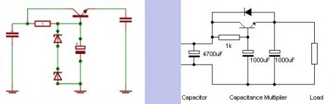
Attached
HRII "zener referenced"capacitive multiplier... vs Rod Elliot basic cap multiplier...
Called capacitve multiplier, as the capacitor at the base of the transistor has it capacitance multiplied by the gain...
destroyer X said:
The circuit used into the HRII is not VBE multiplier
Did you mean to type capacitance multiplier?
I call the "zener referenced series pass voltage regulator" a capacitor multiplier" (something that multiplies gain of a transistor with the capacitance of a cap)
Isn't the VBE multiplier the little "bias servo"? Used for adjusting Bias
Attached
HRII "zener referenced"capacitive multiplier... vs Rod Elliot basic cap multiplier...
Called capacitve multiplier, as the capacitor at the base of the transistor has it capacitance multiplied by the gain...
Attachments

A little slip?
Nordic, the caps are in parallel on each rail of your power supply boards, giving 14700uf each rail. Since you paralled two P/S boards, the total capacitance each rail will be 2x 14700 =29400uf. Since this feeds two channels the average each rail for both channels will be half of 29400 =14700uf
billabong.
boards were not exactly paralleled...
on each side of the ground there are 2 caps in series... i.e. half the capacitance..
One + and one - rail of two old PSUs are tied together to form ground in my prototype..
So form rail to rail I have Rail>capacitor>capacitor>ground>capacitor>capacitor>other rail.
= 1/2 capacitor>ground> half a capacitor...
It was done to use 50V caps at 72V
Thanks Nordic - I thought you might be missing out on sleep again, to mis-calculate it. That was a neat trick with the two P/S boards!
Thanks to you and Carlos for the thorough discussion on P/S capacitors.
I'll go ahead and get the 47,000uf caps.
billabong.
Thanks to you and Carlos for the thorough discussion on P/S capacitors.
I'll go ahead and get the 47,000uf caps.
billabong.
Lucky you, I will have to settle for something smaller, or more creative... The downside of the cap multiplier is that similar to inside the HRII and PI rails it needs to drop a certain minimum amount of volts to make sure demand is lower than the sagging rails under power...
Like Carlos said, it does not need to be so big, it is just that some respectable people claim some benefit.
As bourne by our real word tests 22000uf per rail is more than doble what we used and still semi affordable..
I suppose it is not the wolrd's worst thing seeing that I did not buy transformers for it, but it will probably call for a custom voltage again, which would exlude the few torroids available to me. And to build another monkey coffin case to house the large EIs
before you mentioned those caps, I didn't even know you get such big ones in high voltage...
Looked at Farnells and saw even a 100000uf cap in 63 or 80V... Crazy price though, but nice to know these things exist...
Sorry, i was out from my home.
Left hand is the "zener referenced series pass voltage regulator", it is not very good, as will regulate only till the current you will have multiplying the base current by the transistor gain...so..under small currents, and in special small current variations it works great....only good to input stages, where the current is below 100 miliamperes.
The rigth hand is the Rodd Elliot's capacitance multiplier, excelent to class A circuits as behave as a strong filter, when the capacitance you have into the base appear into the colector, in a virtual form, as the result of that base capacitance multiplied by the transistor gain.... this circuit is no good to Class AB amplifiers, but excelent to constant (almost) current amplifiers. were you have small current variations, do not stabilize voltage very well.
The left hand circuit also has a condenser into the base, and because of that uses the capacitance multiplier effect too..but has advantages into the voltage stabilization because of the zener.
regards,
Carlos
Attachments
- Status
- Not open for further replies.
- Home
- Amplifiers
- Solid State
- Dx Precision, finally released... now debugged and better than HRII