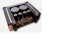
Re: CASE IDEA
Cant´t upload image. Second try
JC Fardo said:Two split heatsink each side, linked by "L" aluminium or straigh bar heatspreader.
Cant´t upload image. Second try
Attachments
Stuey,
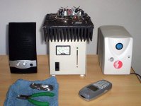
Thanks for the Dick Smith amp chassis link. It is not deep enough for the way I plan to build the P1.
I intend to have the heatsinks on the two sides and with the transformer/s inside too. The depth would need to be 300mm minimum. With Power supplies and 1000VA T/F on the bottom cover 440mm depth would be about right.
Since this will be the last diy amp I will build ( apart from one 3/4 finished), I about decided to buy a ready made one from Thailand, an ATI-731M chassis. I've just emailed for a shipped price.
http://www.atiresearch-anodized.com/ATI-731M.html
billabong.
Re. ATI-731M chassis;
Just received a reply to my email - that chassis is out of stock and they do not know when it will be available again.
So I will have to make my own chassis. I have 3mm anodised sheet, so it will be a stronger case than the ATI-731's 1.5mm. It is a lot of work making lots of ventilation slots/holes though, among other things.
billabong.
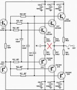
I had the need to try to remove the speaker output from the NFB line
Yes.... i could have better trebles...but the cost was too much big, the amplifier turn unstable and i almost killed some fairchild transistors that i love so much (better gain, better heat transference to heatsinks).
The idea is dead and buried to me.
regards,
Carlos
Yes.... i could have better trebles...but the cost was too much big, the amplifier turn unstable and i almost killed some fairchild transistors that i love so much (better gain, better heat transference to heatsinks).
The idea is dead and buried to me.
regards,
Carlos
Attachments
I have tried to cut here...using switch...micro one into the board.
I have made the test into the HRII...not into the Precision, but i think no good to one will be problem to the other too, as the output is almost the same...the input has differences..but VAS and output is not too much different.
I think result unaceptable.... sounded better, i have used the "same method"... same music, same speaker, same volume, same amplifier, same supply....so switched into the NFB and out from the NFB.... without signal started to oscilate... turn stable having signal.
To me is enougth..... i feel very afraid of those things...if was to myself i could even accept those risks to the better quality and could tweak to make it stable...but i do not want to have something unstable "forced" to stability, as this will go to forum folks....not a good idea to give that possible problem to you folks.
regards,
Carlos
Attachments
You know that everything i do is to listen and evaluate ideas
And to sniff problems too.
I am really not too much curious about the reason why i had that unstability.... in the reality, to me is one more thing i have learned.
Not a good idea to make this modification... others will be needed...so, seems we create the problem to fix them latter...so..better not to create!
It is enougth to me.
regards,
Carlos
Attachments

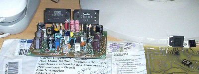
I have received the "lost mail" that was sent from Nederlands
Holland in my language, was Klaas Veenstra that had sent me boards and transistors... a very kind gift from him.
Brazilian customs have blocked and asked me to go there to receive the goods and to pay taxes....and they were bigger in value than the boards and transistors...i decided to keep them there.... apologized to Klaas that understood that had no sense to pay to receive when he had already paid for those goods, and in the reality, those things were not to be understood as business, as they were not really business..just gift between friends and not exportation or importation goods.
One year passed and i have received the mail.... i think they change their mind, or the "bureaucratic" man was moved.... i hope... to hell!... and other one took his place.
Well.... those things are here now, and i am happy, because, of course, Klaas was not very happy with all that thing.... i was not happy also.
regards,
Carlos
Attachments
Hi all,
I'd like your thoughts on the merits, or otherwise, on a power supply arrangement I am considering for my P1. My big Perreaux PMF 2150B stereo amp uses a similar arrangement, except that I would use a Toroidal transformer.
I would use a single Toroidal T/F (1000VA).
The caps will be two 47000uf 80 Volt Mundorf M-Lytic High current caps, supplying both channels. I would probably mount them on the back cover, as Perreaux did, which would allow me to use a smaller enclosure.
I could not see evidence of inductors, bleeder resistors ot bypass caps on the two Perreaux P/S caps, although they could have been hidden under the main circuit boards.
I'm thinking of omitting the inductors, but including the bleeder resistors and bypasses.
The P/S caps would be connected directly to the circuit boards with thick and quite short cables.
billabong.
I paralleld two of the universal supplies used in the DX and HRII... so my capacitance was way below what you have there... and it still worked..
No Nordic.... i am very busy with brazilian folks...decided not to loose the focus
I am on vacation while people assemble Precision 1 boards.... so... i have some time to focus into brazil.
And already have the Precision II..... i do not want to spend my time getting back...i will go ahead.
This idea is dangerous.... and i do not want it...i need safest things.
You can try...go ahead my dear nephew...ahahahha..have transistors to burn?
The damn thing turns amplifier unstable.
regards,
Carlos
Nordic wrote:
So you have shown that a single transformer and capacitor bank (yours were paralled) worked well. I noticed you used 30000uf on each P/S (2x4.7k and 2x10k uf), which gave you 60000uf paralled.
I did consider getting two 33000uf 80V caps, but thought I might as well extend myself to 47k uf. This is my swan song amp, remember.
billabong.
I paralled two of the universal supplies used in theDX and HR11...
So you have shown that a single transformer and capacitor bank (yours were paralled) worked well. I noticed you used 30000uf on each P/S (2x4.7k and 2x10k uf), which gave you 60000uf paralled.
I did consider getting two 33000uf 80V caps, but thought I might as well extend myself to 47k uf. This is my swan song amp, remember.
billabong.
...welll it would be mine too if my wife heard I was going to spend that kind of money on capacitors...
I can get the Mundorf M-Lytics in Australia. Eight 10,000uf 100V Vishay/Sprague Powerlytic caps would only be about AU$30.00 cheaper, landed from the USA, than the two Mundorf's. I think it is worth the little extra cost for the better quality.
My wife is not interested in my hobbies, which is probably a good thing. It could upset her peace of mind to know how much building an amp can cost.
billabong.
My wife is not interested in my hobbies, which is probably a good thing. It could upset her peace of mind to know how much building an amp can cost.
billabong.
Well if does not work well enough by itself, I wonder if it can be used in a capacitive multiplier... I'll see if I can find out...
billabong said:My wife is not interested in my hobbies, which is probably a good thing. It could upset her peace of mind to know how much building an amp can cost.
billabong.
Hmmm, same here. I'm pricing up building Zaph's TMM Waveguide floorstanders using those lovely SEAS drivers. She probably won't be happy... ;-)
Cheers
Stuey
Had a closer look at the Perreaux. The two P/S caps are specially built, 75 (D) x 110 (L) mm 18,000uf 100volt units. The amps are very transparent with clean detailed highs, probably helped by the lowish capacity. Dynamics are still very good though.
So it seems two 22000uf 100volt Mundorfs would be sufficient. They are only AU$10 cheaper than the 33000uf caps and the same size.
I'll probably get the 33000uf caps, but wonder if the smaller ones would sound better?
It appears that Perreauxt take the speaker return directly from the 0 volt connection on the P/S batteries, with what looked like a smaller wire from the speaker output on the PCB to the P/S 0 volt connection.
billabong.
Five thousand microfarads, to each ampere you will have as consumption during maximum
maximum power reproduction..and for each rail... each one ampere to each rail will need 5000uf.....if your rail is 5 amps...then use 25000uf or something alike that each rail.
This value was obtained making real life testings..it is good enougth, and probably more than needed...may be overkill compared to the real need....as i have not reduced to obtain the threshold.
This is normally enougth..maybe even too much...but real life testings show me this can avoid AC ripple noises, modulating your audio, during your operation into maximum power, while having sinusoidal signal, a non audible steady sinus tone into 8 hertz, you will also not listen the mains noises... and this means filtering made his job.
This seems, as you already have noticed, that during other frequencies operation, into the audible range, you will also not listen any noise that may result from not enougth filtering after rectification of the mains 60 hertz AC signal.
This will result, as you know, into a pure low frequency reproduction, as 30 hertz will be only 30 hertz and not 30 hertz together mains hum noises.
Simulator results, published, show the maximum current to each rail, during sinusoidal, continuous, input testing....and i have made them real life too... and resulted silent sub sonic tones (not audible), but speaker moved forward and backward and i could not listen (1 meter distance, in front of the speaker, ears level) the mains noise....so, folks, multiply each one ampere by 5000uf, and do that to each rail, to maximum power into 4 ohms, and you will be safe.
Randy Slone also have concluded something alike that.. i just do not remember if his value is the same i have found.... i suppose his value will be bigger, as bigger will be more safe to someone that is publishing a book and want it to be some kind of safe source of informations.
I will check what he said...was something about 10 watts and the condenser to each 10 watts of power...will check soon.
A good idea is to use bleeder resistance to discharge big condensers, and to use bypass capacitors, at least, one each rail.
Do not believe me, or Self, or Slone.... always test by yourself, this will be good for you and for our community, as we gonna be not "believers"..but people that really knows the thing.
Use big resistances as load... and from this load resistance run 330 ohms resistance to a good headphone.... then inject 8 hertz tone...not audible..just air pressure into your ears...you will feel the air...increase the volume till the clipping..you will listen the effects of squared waves..those noises will be listened,as they are not 8 hertz only..... reduce to avoid noises and try to perceive low frequency, the mains tone.... into the headphone you may listen a very small level, but be sure that 1 meter distant from the speaker you will not be able to listen.... so small will be the ripple level....observe that headphones are near your ears and damping the external noises, so...your brain plus ear system will operate maximum sensitivity to listen small level tones... this is not really real life, but more sensitive to listen noises than real speaker reproduction, 1 meter, of much more than that (normal distances) of listening.
regards,
Carlos
My method resulted in 18000uf each rail minimum condenser value
The amplifier produces 264 watts undistorted over 4 ohms, unclipped, continuous sinusoidal tone, 1 Kilohertz, if supply is maintained at 64 volts (non dropped theoretical supply) into the output and 56 volts into the input circuits.
I have checked Randy Slone book, he said 1000uf to each 10 watts... this means the filtering, in his point of view will be 26.4 Thousand microfarads.... and this is to each rail.
So.... Doctor Slone said 26400uf each rail, he said his method is self indulgence.
My idea is 18000 each rail..but i have not tested the lower limits about that....so, now you have more references to think about and to decide.
Remember that very experienced folks use to say, at least they told me into conversations, that big condensers use to muflle treble.... despite this do not enters very well into my mind, i had found, several times, that those friends really knows what they are talking about...so... despite i have not that "muffling" experience by myself, i use not to exceed 5000uf each ampere, and to each rail, to be carefull about things i have not the real life experience.
I think if we are not sure, if this muffle sound will happens or not, better is to make testings, or if you do not want to make testings, a good idea will be not to take the risk.
regards,
Carlos
- Status
- Not open for further replies.
- Home
- Amplifiers
- Solid State
- Dx Precision, finally released... now debugged and better than HRII