Great news... was ordering parts before, therefore I asked. But now it's too late, couldn't wait any longer  well, I think parts are not the real problem
Sorry for posing with that 😀
 well, I think parts are not the real problem
An externally hosted image should be here but it was not working when we last tested it.
Sorry for posing with that 😀
😉 Well pm me your address 😉 Just stuff from surplus, me a lucky guy 😉 hmmm, beach and sun...
Well, back to the topic😎
If I supply the precision with a lower voltage (I have just a 2x50VDC supply here, next thing is 2x75VDC..), what difference must the Input stage against the Output stage have, just 63-55V?
And I don't want to see those radial 1000µ on the board 😀
Thanks Carlos, you're one person with a character all of us should have ! not joking...

I felt myself confused with your answer dear friend
Please, try once again....will you operate with 55 volts?
Do you want to use 64 volts left amplifier side and 55 volts to power output?
Or you want to have 64 volts to the power unit and 55 volts to the left amplifier side (differential and VAS circuits)
I am confused..sorry...me stupid!
It is hot here Weissi.....my daugther was into the beach last weekend.... temperature is pretty to watch people into the beach but is something that cook everything you have...you know.... that thing cooks too!....because pants, shorts...you understood..very hot weather..not good!
regards,
Carlos
I have prepared images to help Nordic and all folks to assemble
and then, debug problems that normally happens when we assemble amplifiers.
We always make some mistake..this is normal, this is human...because of that we are working hard, preparing boards to avoid too much problems.
Because, even with boards, we can assemble transistor with wrong pins..inverted, or we can put NPN in the place of PNP.
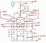
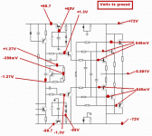
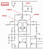
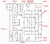
I have splitted into 2 images...amplifier left side and amplifier rigth side.
And you will have voltage left side and voltage rigth side
will have current left side and currente rigth side
will have VBE left side and VBE rigth side
will have modification rigth side and modifications left too.
I hope you understand what i have done....i have removed part numbers and values not to confuse..just showing you points and informations about those points indicated using arrows.
regards,
Carlos
Attachments
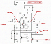
Well dear friends, voltages are measures with the black probe point
fixed into the ground... with solder or aligator clips.
then you measure with the red probe point.... with a digital multimeter voltages positive and negative will appear into the display.
Those voltages are the ones i am informing you.
This amplifier is using 72 volts supplies to power and the rail regulator are descending to 62 volts...a special sittuation, something dear nephew Nordic is testing in his home rigth now...he is using 2 transistors pairs into the output, to operate 8 ohms only...the idea is to test board layout.
Those voltage are sligthly different.... not the standard voltages suggested, and this, off course, will make some difference into the measurements, but not so huge as we can think...only the power transistors and drivers are into the positive rail and negative rail..so..theres you gonna have differences....but into VBEs and currents the differences will not be so big and the voltages will be helpfull to you even using different voltages.
Voltages there "makes sense"...so.... you can see, they are what you spect into those positions..nothing extraordinary into those voltages.
regards,
Carlos
Attachments
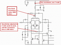
Current as measures in series with the circuit..so..you have arrows and points
The current is measured opening that point in installing the amperometer in those points.... an intercepted line has two points...so...one probe to each point.... 200 miliamps DC scale and check currents.
More normal currents are from colector to emitter..the ones interests us to measure, as others are very small and they are more controled by junctions and bias circuits.... the result of biasing circuits will have, as consequence, colector to emitter currents that you will measure to know if everything is running fine.
regards,
Carlos
Attachments
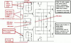
People love to know currents because shows circuit conducting.... and more than that
allow you to calculate power to resistances and transistors.
Power is current multiplied by voltage.... expressed, written in Amperes and Volts.... so.... 10 miliamperes is 0.010A ... and 545 milivolts is 0.545V
So, you will see that some resistances will need bigger values about heat dissipation....some will be 1 watt, and other 2 watts...and the biggest majority will work fine with half watt and 1/4 watt (or something around that).
The transistors, the rail voltage regulators, drivers and CCS transistors, also the Master VAS..all them are having 1.5 watts or something alike.
But have to increase, because this current is into the stand by mode, without signal.... when you introduce signal, some of them will have some increase and decrease of current following the audio swing...because of that, think on them as 3 watts each one..and this means 30 square centimeters aluminium exposed to the air (one side calculated, not both sides added)..means a piece of aluminium, lets say squared, around 2 inches the side dimension, around 5 centimeters...and those heatsinks can be made into "U" shape, it "L" shape or anything you find reasonable.... 2 small units back to back... two U shape back to back will work too.... you can even try a half of that..but you will feel some heat into the transistors..and this, into the drivers, can cause to you problems as temperature drift.... current because of that goes increasing while the amplifier is going to be hot.
I love printed circuit heatsinks, using the copper...lovely idea Nordic had..but to this amplfier...really...no way!
regards,
Carlos
Attachments
No, I meant that 63V is the total supply, whereas the 55V are meant to be the sum of the Z-diodes 22V and 33V (so I call this the input stage voltage..)
Thanks again Carlos.
Edit: Huh, Am I slow....?
Thanks again Carlos.
Edit: Huh, Am I slow....?
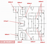
Now VBE .... and this is voltage from base to emitter
Measured with one probe point into the base and the other into the emitter.
Good idea is to use heatschrink tubes to insulate your probe tip.... left just one milimeter uncovered to touch the transistor leads, this will avoid shorts..a short from base to colector send the transistor to hell immediatelly!
It shows how the transistor is biased...how advance it is into the limits of operation...they start to conduct around 450 milivolts and normally we do not use above 700 milivolts....the most normal sittuation by the books is 650 milivolts.
My multimeters, and life experience show me that 550 to 610 milivolts are the more common voltage you will find into amplifier..beeing 575 the more common sittuation..and this shows it is fine!
regards,
Carlos
Attachments
People usually do not bother with VBE and some of them do not like,
But really show you how the transistor is operating.
Imagine you find a transistor with 450 milivolts of VBE.... now you inject audio into the unit...the positive going audio will make those 450 milivolts increase...no problems!..this is normal work..but the negative going audio will make it reduce to less than 400 milivolts and the transistor will switch off causing noises and distortions..so..... 450 milivolts, depending the audio will enter, can be no good!
Imagine, as second option, that your transistor has 650 milivolts..already very biased..heavy bias...and now a positive going pulses of audio swing enter and increase the voltage...well, the unit will saturate and will cause distortion.... the oposite negative audio will not create problems.
So..better not to be into the North Pole and not good to be in South Pole.... reach Equator and you will be more happy!
ahahahahh!
regards,
Carlos
Attachments
Thank you dear Carlos... it is me and the board again today...
Lets hope you are right about the inverted transistors...
Allthough experience and prototype do suggest that Iwill have to modify layout AGAIN... hahahah to cope with extra heatsinks for the medium transistors, they just run too hot without.
Planning to work at great speed today... As I want to also prepare and test the new adjusted layout today.
P.S. I actually am useing 3 output pairs, that photo was just a test fit... the transistors are supposed to go flat on a piece of angle stock... I cheated which is ok for testing....
And the axial cap's holes are underneath the radials.... used what I could get.
I am glad the explanations will be helpfull.
Todd, tell me once again your supply voltage, so, i will simulate to see the real power...hehehehehe.
And you decision about number of output "guys" aligned as soldiers (pretty thing those transistors aligned)... or if you wanna suggestion about the number of Transistors.
I feel you will use them hard...and over 4 ohms....heheheh..will be a demolition into your home.
Tell something i always wanted to ask..... USA and Canada use houses made by wood ( (I feel that interesting but really crazy..here an idiot will ligth a match to see what happens...and will happens for sure).... do those woods, fixed with special things, high pressure, high quality pneumatic machine with nails and all stuff do not vibrate, do not ressonate with powerfull sound?
regards,
Carlos
....................................................................................................
I am happy you are working hard into the Precision 1 dear Nordic, also very happy about holes to radial units behind the whale tubey thing there...aghahahahhahahahahah!
Parts are very near one each other...maybe to give to parts room to populate the entire board can be even more interesting, not only to repair (as everything can burn and need repair), but also to have some "air around"...let's say, to allow population to breath fresh air..... people are together (parts near one each other) alike people into a crowdy bus or a Japanese train going to work exactly at 7:30 (they appear from nowhere in number of hundreds... all them same time!)
Yep.... something there is inside chapters of Myths....beliefs..... people say that connections have to be short.... yep...they have to be short..but watch computers with higher speed how long are the connections that goes twisting surrounding boards.... we are poluted with a lot of "be carefull" and sometimes this turn us obsessive into some details..... you can give room to parts and i guarantee nothing will oscilate.... my worries about oscilation are more because things people say than my own life experience..so hard to make so big mistake that result into oscilation that i even do not believe this will happens....but, of course, i am experienced, skilled as a hell into those subjects...lines in parallel use to have coupling one each other..better to cross lines... waving lines can turn a coils...good to avoid.....small distance between lines creates capacitors, good to avoid..but also parts near one each other can have coupling..good to avoid and create, at least, 4 milimeters distance between them...parts cannot touch one each other, even insulated...well..there are very basic rules that i follow automatically, but really others can make things oscilate...i am very unable to do that.
regards,
Carlos
Hi Carlos
Back when I was in school, I built a powered sub box for the house I was living (sharing) in. It had a 15" Fosgate Series 1 speaker(I loved these old subs, they sounded delicious), about 100WRMS max, and was a ported band pass box, with 1/4" plexi on the front and top. Resonant frequency was about 33Hz. It even had a black-light mounted on grommets inside.😛 When it was thumping in the basement, I could go to the neighbors house and here it, just that box, inside their house. But, you couldn't here it outside. The sound must have traveled in the ground and up through the foundation of their house. You could here it quite well over there, but all was well as they were usually at our parties anyway.
Back when I was in school, I built a powered sub box for the house I was living (sharing) in. It had a 15" Fosgate Series 1 speaker(I loved these old subs, they sounded delicious), about 100WRMS max, and was a ported band pass box, with 1/4" plexi on the front and top. Resonant frequency was about 33Hz. It even had a black-light mounted on grommets inside.😛 When it was thumping in the basement, I could go to the neighbors house and here it, just that box, inside their house. But, you couldn't here it outside.
 The sound must have traveled in the ground and up through the foundation of their house. You could here it quite well over there, but all was well as they were usually at our parties anyway.
Interesting story CBS240, thank you to share the experience with us
Was good to read your text.... life experiences, those things are precious.
thank you,
I have watched a movie reading your text.... a rarity, as people is only technical...very rare and precious things.
A pitty.... finished very soon.
Nice.
Carlos
Was good to read your text.... life experiences, those things are precious.
thank you,
I have watched a movie reading your text.... a rarity, as people is only technical...very rare and precious things.
A pitty.... finished very soon.
Nice.
Carlos
Hi Carlos,
One choice of transformer I have (the closest to 63vdc) for Precision would provide ~74vdc rails (no load), my speakers are 4-ohm nominal. Existing chassis/heatsink (from a Bryston 4B) has room for 4-pairs of output transistors per channel. I don't intend to listen very loud, just recycle my old hardware. (Unless the neighbours tell the police I'm building a grow-op again -- grrr.)
Off-topic:
Yes, wood frame houses can vibrate/resonate at many frequencies all at once. But they are usually very well braced and damped with plywood, gypsum board and fiberglass or rockwool insulation, so vibrations and rattles are not usually a big problem. Room size, shape and surface materials are much more of a consideration with acoustics -- same as with concrete/brick structures.
Wood frame houses are more flexible, much less brittle than concrete and are therefore safer in earthquake zones. And they are warmer to the touch in cold climates.
Yes, they burn better than concrete. But we resist the urge to have campfires in our living rooms. (Idiots and accidents notwithstanding.)
And yes, they use powerful pneumatic 'nail guns' to assemble the house frames. Hammers also, where the nailers won't fit.
..Todd
- Status
- Not open for further replies.
- Home
- Amplifiers
- Solid State
- Dx Precision, finally released... now debugged and better than HRII


