Well, sensitivity was adjusted to 750 milivolts RMS, and i imagine good for DVD
output and CD output.
But, as you use, during testings, the Ipod...it is possible to have low sensitivity to it as you have told me in direct mail.
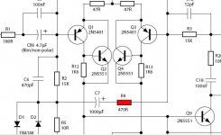
We have R4 to adjust the sensitivity..so..if someone needs more gain, more sensitivity, if not reaching high power with audio source adjusted to full volume, than you can reduce R4 to 390 ohms or 330 ohms, 270 ohms or even 220 ohms if needed.
I suggest to keep the standard value for a while as we will already have to adjust R27 to 180 ohms, as the value show was a mistake because of Precision II that use this small value there..but with other driver current feeded by a CCS.... higher current than Precision I
Well... now one more step advanced.... board already had preliminary test..so... seems layout is safe.... next step is to test a board made into the factory and to release the Precision I to everybody.
I am glad you have appreciated dear Nordic.
regards,
Carlos
output and CD output.
But, as you use, during testings, the Ipod...it is possible to have low sensitivity to it as you have told me in direct mail.
We have R4 to adjust the sensitivity..so..if someone needs more gain, more sensitivity, if not reaching high power with audio source adjusted to full volume, than you can reduce R4 to 390 ohms or 330 ohms, 270 ohms or even 220 ohms if needed.
I suggest to keep the standard value for a while as we will already have to adjust R27 to 180 ohms, as the value show was a mistake because of Precision II that use this small value there..but with other driver current feeded by a CCS.... higher current than Precision I
Well... now one more step advanced.... board already had preliminary test..so... seems layout is safe.... next step is to test a board made into the factory and to release the Precision I to everybody.
I am glad you have appreciated dear Nordic.
regards,
Carlos
Attachments
Well... i can be wrong...but it seems to me that Line out level and impedance
the one we find in CD players, DVD players, Monitors, computers line out plugs and others are the standard.
Also the standard in level and impedance are the Pré amplifiers, and a lot of folks use them, because needed, to play Vinyl discs.
Because of that the sensitivity was adjusted this way but up to you builders, to decide the way you want and to adjust in such a way make you happy and matches your audio sources.
Here is the resistance was changed.... near future i will ask Todd Johnson, our friend TAJ from forum, to change this value and we gonna wait some days to see if something more will need to be modified to make the modification just once.
R16 will need the 2Watts mark on it...also R6 will need to be marked 1 watt and we gonna inspect more details too.
regards,
Carlos
Attachments
Be attention boys!.. this one will need replacement
A new value is 180 ohms
Was a mistake, because the Precision II.
Value correct is 180 ohms.... with the previous you have underbias into the output.
So, when you increase the main bias control you will have to produce too much current into the drivers (high VBE) while the output shows 480 milivolts only.... now, the VBE voltage is shared in a better way and you can adjust to from 2 to 5 miliamps to each power transistor related the colector to emitter stand by current.
regards,
Carlos
Attachments
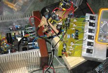
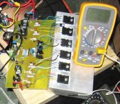
You have busted another old Myth dear Nordic.
People use to say that wires connecting transistor to boards causes oscilations.
And you have a stable amplifier...i always use this method even with bigger lengthes.... i have used 5 inches and wire was twisted one with the other and never had problems.
Of course not the prefered way..but you have busted another Myth.
Good....showing reality, home constructions, we show that a lot of Myths are not really truth.
Of course... small lengthes will be better...for sure....and better to be very short...but amplifiers works in other ways too..and sometimes (not always) very stable.
Romantico la construzzione la basetta di legno!
Romantic you have used a piece of wood...nice that!
regards,
Carlos
Attachments
When i start to read the forum, the Solid State, my prefered and the only one
visited daily and many times a day, i was very shocked with the enormous care, worries and concerns people had with short wiring and that stuff.
Boards, no curve lines, capacitances and inductances..and so on.
And i came from the Radio Amateur World, giving a break in Radio Frequency and re-starting my old passion...audio amplifiers.
And i felt very strange and i used to ask to myself if those worries could make sense.
I found that had not sense... the inductances and capacitances present into a board are small in value..and when you combine inductors and capacitors you make a ressonant system... a tuned system, and this creates oscilations because it is the nature of those things to work this way, charge and discharge timing produces that time constant...but always into the Very High Frequency spectrum.
And i used to ask to myself.... are they using Radio Frequency transistors... and i found that some of them were using, but not all them...so..only the ones used Radio Frequency transistors have to worry because of boards.
And this is what happens...if we decide to use audio frequency devices to audio frequency we will never have troubles related boards, length of wires and that stuff.
So.... people had created the problem and them created the second problem to fix the first one...worries with board not to oscilate because the put "Oscilating things"... into the board.
I have strong problems to believe that there's someone that really imagine that audio will be better. (20 to 20K) if they use transistors able to work into 250 Megahertz range!
Well... well...well.
Carlos

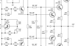
Todd Johnson, our TAJ, sent me the final schematic
Revised.
Very pretty work made by Todd...he is very good with Adobe Illustrator... his work quality is excelent.
Thank you Todd!
Schematic is attached.... drivers goes to heatsink, also VBE multiplier transistor goes too.
All other mid power transistors use heatsinks... and will be good not to use the smaller ones... dissipation there goes to 1.5 watts into stand by mode.
I hope you enjoy...
This amplifier has special dinamics, big power, excelent deep and controled bass , the special, very special voices and have less good treble compared to HRII... sligtly mufled compared....nothing that a good speaker, a good audio source ad a good tone control cannot fix.... when you increase treble 3 decibels it sounds so good and present, as the HRII.
You can reduce compensation...but lower than 47pf you may have oscilations...also you can remove C10 or R9...you will have difference even in sound stage.
But in the reality, you perceive better ballance of tones when you reduce input condenser to 4.7uF.
So... adjust it to your taste and enjou an excelent sound amplifier.
If you want something better...go to Aksa...i have compared...treble is better...well.... Hugh is better...we know that..he is my teacher... the Audio Amplifier King.
I use to do my best..but to beat Hugh i will have to eat better, to make exercises, to fix some damaged neuroniuns and to increase blood circulation in advance... Hugh is even more healthy than i am.
regards,
Carlos
Attachments
Carlos, heatsinks on Q11 and Q12 are unnecessary.
The collector current is ~20mA, the Vce is ~8V. Then dissipation is ~160mV.
Rth j-a of the device is 100°C/W, so even at 30°C ambient temperature the temperature of the transistor's case without any heatsink would be 30+16°C=~45°C. That's fully acceptable.
The collector current is ~20mA, the Vce is ~8V. Then dissipation is ~160mV.
Rth j-a of the device is 100°C/W, so even at 30°C ambient temperature the temperature of the transistor's case without any heatsink would be 30+16°C=~45°C. That's fully acceptable.
In theory yes, but with any of a number of errors, they get realy hot, realy quickly....
Carlos is aware of the dissipation, previous prototype was in fact built without those sinks, and they are included on my insistance now.
Carlos is aware of the dissipation, previous prototype was in fact built without those sinks, and they are included on my insistance now.
Carlos, Nordic and Todd, thanks for all the effort you have put into the Precision 1. I'm sure it will be a great success.
I look forward to building it. The midrange is one of it's strong points it seems, which is a great result. I expect the treble will also be fine, if the P1 is mated with a high quality front end (Vinyl in my case), speakers and wiring.
Regards,
billabong.
I look forward to building it. The midrange is one of it's strong points it seems, which is a great result. I expect the treble will also be fine, if the P1 is mated with a high quality front end (Vinyl in my case), speakers and wiring.
Regards,
billabong.
Thank you Billabong.... i hope to have you with us
Francis
We know how to multiply current by voltage from coletor to emitter my dear.... also to observe datasheet.
Sometimes real world do not confirm our thougths, then we prefer to obbey what we find into real world testing.
Heatsinks are keept as standard, of course you can remove them from your units if you want dear Francis
Thanks Nordic.
regards,
Carlos
High frequency quality:
Using a Black Gate non-polar input cap (CIN) bypassed with a BG NX HiQ 0.1 uF (C5) would I think help improve treble performance. Carlos has already suggested using BG as CIN.
I found the treble improved noticeably when I previously bypassed BG N with BG NX HiQ. Martin Collims recommends BG NX HiQ as bypasses.
billabong.
Carlos, I squarely wanted to help, not to tease you. No one wants to brief you, to slag you!
I credit that you know how to calculate the case temperature of a semiconductor, but I tought that you overlooked something, you made a mistake during calculation.
I'f such technical comments are uwanted, tell me that. Then I'll leave your thread placidly.
On the margin 45°C is 45°C. Both in theory, both in the real world.
PS.: Francis is my surname, my forename is Andrew. Please call me Andy! I know in an international forum like this names are always problem.
Hi Andy, I am sure Carlos did not mean to offend.
Allthough he uses the right words, his knowledge of english sometimes does not help him fully appreciate the tone of the direct translation... he is very much portuguese
Billibong, the board was designed to handle the 8mm 10uf BG if needed...
Allthough he uses the right words, his knowledge of english sometimes does not help him fully appreciate the tone of the direct translation... he is very much portuguese
Billibong, the board was designed to handle the 8mm 10uf BG if needed...
Nordic said:Hi Andy, I am sure Carlos did not mean to offend.
Allthough he uses the right words, his knowledge of english sometimes does not help him fully appreciate the tone of the direct translation... he is very much portuguese
Then I apologise to Carlos, I wasn't discreet enough when I wrote my post. This affair was only a misconception.
Nordic, thanks for the exposition!
As Shakespear said "Much ado about nothing" 😀
Parts list for Precision One is over here. for those who do not have Office installed.. (you will need to sign up for a google account - free)
Alternatively you can grab the file attachment if you have the software on your PC.
Parts list for Precision One is over here. for those who do not have Office installed.. (you will need to sign up for a google account - free)
Alternatively you can grab the file attachment if you have the software on your PC.
Attachments
- Status
- Not open for further replies.
- Home
- Amplifiers
- Solid State
- Dx Precision, finally released... now debugged and better than HRII