Andy L. Francis
The voltage suggested is 64 volts...but the amplifier is able to hold more voltage into the power side.... into the power circuits.
Sometimes folks have supplies that measure 75 volts without load, and those supplies goes down to 67 volts under load conditions... using those kind of supplies the transistors goes to be very hot into real life and 30 degrées celsius environment (very different than 25 degrees you see into the specifications).
Nordic have used 72 volts supply to test the amplifier.... this way you see that will happens the same with people that have already assembled Dx Standard or the HRII. Those folks have 2 supplies with 35 volts each one of them, and this can be modified to a single 70 plus 70 volts supply.... this way, my dear friends that have already build Dx Amplifiers, are able to make the Precision without the obligation to buy transformers.
The amplifier is not anymore into the design moments, all calculation was already made and was tested many times in many models..real life testing and finger-o-meter observations of temperature as also the Multimeter with thermometer probe tip.
So... was done... was checked, was decided this way my dear..just that... telling real things...just that.
I do not want to recalculate each circuit to check what i have already made because this waste time, and i have already made that...Nordic too.
As people may want to use 70 volts supplies, simetrical obviously, the heatsink into the transistors are a need... and if not a technical need, they turn more pretty using them, and also keep them all with their own heatsinks.
Factories, transistor factories, as you know, test the units using big machines... enormous metalic holder that are maintained with machines into 25 degrées celsius.... so... this small BD139 can dissipate the heat, in accordance the numbers you have found into data sheet, if you keep them into 25 degrees celsius, and this is not the correct temperature it will work into the South of our Globe those monthes and will no found into your place during summer time too.... so.... the data we have are not good enougth to reality.
I use to reduce people's name, this is a common use into my place to make people more close, more in touch, more friendly way to call them.... Andy L. Francis is very hard to type....i had not intention to offend you Mr Andrew.
You are not in charge to re-design the amplifier my dear... already made..relax, take your chair and enjoy the sound of the Dx amplifier...the hard moments of calculations, testings, adjustments already finished..you do not need to spend time with that, unless you do this as and exercise.
regards,
Carlos
Carlos, thanks for the detailed comment, particularly for the kind words in the end of your post.
I wish you many successful amplifier projects! Keep on your beneficial work!
I hope you at peace with me now. You can always fall back on me (although my knowledge is limited - as every human being's knowledge is limited).
I wish you many successful amplifier projects! Keep on your beneficial work!
I hope you at peace with me now. You can always fall back on me (although my knowledge is limited - as every human being's knowledge is limited).
Excellent news! (The BOM I mean). I can start ordering components now. I look forward to building this well-regarded amp.
Carlos & Nrdic,
The image in post 569 by Carlos showed a fuse in the centre of the board, which I can't see on the schematic. Was this image not totally accurate?
Also what are the recommended ratings for fuses F1 & F2?
Regards,
David
The image in post 569 by Carlos showed a fuse in the centre of the board, which I can't see on the schematic. Was this image not totally accurate?
Also what are the recommended ratings for fuses F1 & F2?
Regards,
David
Hi StereoDave,
The 3rd fuse (on the output) is correct. I didn't notice it in the latest prototype layouts, so I missed it, along with the output section bypass caps. I have updated and re-submitted the schematic so once Carlos and Nico have a chance to check it out, they'll either post it here as is, or I'll fix wut needs fixin, and it'll end up here soon regardless.
..Todd
In this image you have an idea about fuses
I suggest you to put three fuses.... defects into the circuit use to send rail or rail to rail voltage into the output....and this can kill speakers (of course)
So... a fuse may be very good to protect your speakers, and it will work if your speaker is rated to hold this power level.
The 64 volts supply is a suggestion only... also the voltage reduction is a suggestion only.... this will depends your transformer behavior under load conditions...so...if you want to know how it will behave, try to load it to drain 2.2 amperes, for instance, and this way you will evaluate how it will work under load.... the voltage will go down, for sure will go down some volts.
Because of that, you may decide your fuses in accordance to YOUR own reality.
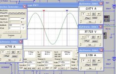
Left side you have Amperes, alternate current amperes.... the scope is clear that is not distorting, it is into the threshold...maximum power before clipping (yes, has distortion of course, but not the clipping result ones!.... has harmonic and intermodulation for sure)
At rigth side, and upper, you have Amperes DC, rail amperes DC under maximum power consumption before clipping...normal undistorted sound this one..... not clipped sound...the one normal to be used.... highest possible reasonable volume to listen.
Center is the voltage AC measurable over the load...this is AC RMS..so..apply the basic calculation.... squared and divide by the load impedance.
At rigth side, and lower, you have Amperes DC, rail amperes DC, this one negative rail amperes DC, under maximum power consumption before clipping, normal undistorted sound this one, not clipped sound, the one normal to be used....highers possible reasonable volume to listen....or the peak of power, measured into RMS, of undistorted audio power.
This one is 177 Watts RMS over 8 ohms
regards,
Carlos
I suggest you to put three fuses.... defects into the circuit use to send rail or rail to rail voltage into the output....and this can kill speakers (of course)
So... a fuse may be very good to protect your speakers, and it will work if your speaker is rated to hold this power level.
The 64 volts supply is a suggestion only... also the voltage reduction is a suggestion only.... this will depends your transformer behavior under load conditions...so...if you want to know how it will behave, try to load it to drain 2.2 amperes, for instance, and this way you will evaluate how it will work under load.... the voltage will go down, for sure will go down some volts.
Because of that, you may decide your fuses in accordance to YOUR own reality.
Left side you have Amperes, alternate current amperes.... the scope is clear that is not distorting, it is into the threshold...maximum power before clipping (yes, has distortion of course, but not the clipping result ones!.... has harmonic and intermodulation for sure)
At rigth side, and upper, you have Amperes DC, rail amperes DC under maximum power consumption before clipping...normal undistorted sound this one..... not clipped sound...the one normal to be used.... highest possible reasonable volume to listen.
Center is the voltage AC measurable over the load...this is AC RMS..so..apply the basic calculation.... squared and divide by the load impedance.
At rigth side, and lower, you have Amperes DC, rail amperes DC, this one negative rail amperes DC, under maximum power consumption before clipping, normal undistorted sound this one, not clipped sound, the one normal to be used....highers possible reasonable volume to listen....or the peak of power, measured into RMS, of undistorted audio power.
This one is 177 Watts RMS over 8 ohms
regards,
Carlos
Attachments
billabong said:High frequency quality:
Using a Black Gate non-polar input cap (CIN) bypassed with a BG NX HiQ 0.1 uF (C5) would I think help improve treble performance. Carlos has already suggested using BG as CIN.
I found the treble improved noticeably when I previously bypassed BG N with BG NX HiQ. Martin Collims recommends BG NX HiQ as bypasses.
billabong.
Why not just use a BG NX and then no by-pass cap is required. I have these at the input on 2 amps from a highly respected designer.
But we have to think about those fuses
They are not fast
They are not precise.
So, it is a good idea, as nobody will put steady tone into maximum undistorted power (maybe not.... maybe yes... i suppose not!), so, you have to rate fuses lower to really be protected.
But, my way to do the things do not hold many seconds playing full distorted volume or steady tones..... this is my use, you decide the way you believe as better to your own use..it is up to you decide that my dear friend.
Into 8 ohms, my own amplifier, my home use, i would use 2 amperes rails and 3.5 amperes output.
WHY?
Voltage will go down...and the output will be smaller than the one the simulator shown...and this depends form the transformer, so i cannot elect a series resistance into the supply to achieve a more precise result as each transformer may behave different..... if voltage goes down..power will go down too... and even with 3.5 amperes, normal music, you will have a good fuse value...and if something goes wrong, 3.5 amperes fuse is better than 4.5 or 5 amperes fuse... will burn sooner without melt speaker coil.
Here, the image to 4 ohms.... you decide your fuses boys
Into schematic will go 2 amps to rails and 4 amps to output... to avoid the worst case....my home i make this stuff better.
regards,
Carlos
Attachments
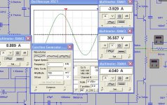
To 4 ohms operation....then 4 amperes for the rails
and 8 amperes for the output.
I hope you enjoy the sonics.
God bless your speakers my dear friends.
Have you said good bye to them?
regards,
Carlos
and 8 amperes for the output.
I hope you enjoy the sonics.
God bless your speakers my dear friends.
Have you said good bye to them?
regards,
Carlos
So, my dear Canadien Friend Todd Johnson, Dx Corporation Art Departament
Please, into the schematic, put:
Fuses to rails and fuse to output
To 8 ohms use:
Rails with 2 amperes fuses and output with 4 amperes fuse
To 4 ohms use:
Rails gonna be 4 amperes fuses and output will be 8 amperes fuse
Thank you in advance dear Todd.
Do not have those fuses values?
So use the one you have.. the nearest value.
Also solder a very thin wire....as a link under the fuse holder or other place... this is to avoid defective fuses to introduce resistances into the rail power voltage.... for sure if some big current happens, not only the real fuse will melt..the very thin wire fuse will melt too..so, will not bother you too much..may introduce more 300 miliamps to your fuse power only.
Dx Corporation cooperators, stuff and customers use to be reasonable handsome... also they use to be faceless, they love to post their images to the Historical Room in the future Dx Corporation Headquarters....you are historical testimony, take you place into the honor hall!
regards,
Carlos
Attachments

You said Rabbitz!... will be done...and immediatelly!
Please dear Todd... proceed the substitution of the input condenser by a nice Black Gate.
You live in my heart Rabbitz....you desire is an order to me... tell me if something more must be changed.
The use to sound better, those black gates, for sure.....my mistake!
regards,
Carlos
Please dear Todd... proceed the substitution of the input condenser by a nice Black Gate.
You live in my heart Rabbitz....you desire is an order to me... tell me if something more must be changed.
The use to sound better, those black gates, for sure.....my mistake!
regards,
Carlos
Attachments

Oh!...sorry dear Rabbitz, as bypass i will keep the things made not to give
another step back.... dear Nordic is perfeccionist and he may make all board again, and this will delay many days...also will have to bother Todd to change all that stuff to simple black gates instead of electrolitic condensers and capacitors.
So, if you can forgive me, i would prefer to keep the way it is now.
I hope Nordic do not read that....he is very obsessive by perfection into the baord layout.... he may start everything once more and people are waiting for those boards.
regards,
Carlos
the board was designed to handle 8mm, 10uF Black Gate if needed...
That's handy Nordic, but because I mainly play Vinyl and have large double ported bass reflex speakers, I will not likely use larger than 4.7 uF, and may need to go as low as 2.7uF (Black Gates).
Cheers, billabong.
Sorry Rabbitz, i love Nordic deeply, but he is very obsessive
He is that kind of milimetric guy, worries with very small things..ahahahaha... he may make a good partnership with our friend Andrew, that is also perfeccionist too.... i am still thinking to send dear nephew to Nort England, as he will find his master there.
Both love things perfect and Nordic is searching of the best point to pick the copper line... the best feedback point!
Doctor Self told that...and he is a respectable man...but i think he had returned from a party and had some wiskies when he wrote that page into the book.... too much for me...in excess of delirating ideas.
People are worrying with standing wave problems (SWR)... when standing wave appear into radio frequencies... they are deviating, re-directing this to audio too?.
I really hope he will not read that..or i will have problems with him (Nordic).
I wish God can give me more patience and tollerance.... my God...the board will start over again!!!!!
Nordic may say (my worries are about that)
- "Hey uncle, don't you think that we shoud replace the pair, electrolic condensers and capacitors, to a single part as YOUR FRIEND SAID, and you wanna do what he want,... and he is friend, he is good, he is customer, he is handsome, he likes dogs... as we like...lets do it?... let's do it?.... let's do it?
We are delayed... amplifier released 24 December 2007 and we have not offered boards.... Dx Corporation will have to change the name to Dx Turtle Corporation!
Have watched the movie the guy complained about God and had elected to be God while the real one gone to vacations?
I would like to make a movie that way...but i would put more wind to see the dresses flying up... and also with Latine women too...but more.... 6 to 10 in fast sequence..... by slow motion fast shots!
I am feeling alike that guy!.....
Asking guy?
- "Do you think this is funny?... do you think this is nice?... to send my friend Rabbitz to tell that stuff into the thread?... and Nordic will read that!... is that you want to me God?... to drive me crazy!......."
ahahahahahah!
regards,
Carlos
Sometimes SOMEONE needs to think detailed... no point in the schematic calling for 10uf, and someone pitches up with a 10uf BG and it won't fit...
I think the caps you mentioned you wanted to use is more than enough. Personaly I will also stay in the 4 to 7uF range for now (small house).
Lol, Carlos, no, my patience also only stretches so far... I guess it is like an artist knows when a painting is done... it just feels right.
P.S.. I have never referenced a friend, you said yourself you do not have scientific approach, some of us do... When something seems like a direct opposition I expect both sides to be able to state their cases... failing which I go with the one that makes the most convinceing arguement.
I have asked some of the more respected guys (i.m.o.) a few questions to see how it matches the information at my disposal.
But this is usualy after haveing done what I felt needed.. kind of like a second opinion...
In the mean time I invite you to learn eagle... when you are up to my standard you will know just how much time it takes to get there...
rabbitz wrote:
That would be fine if you can source them in the values we need. Supplies of Black Gates are running out fast. I just looked and could only come up with 4.7 uF and 10 uF 50V BG N. The 0.1 uF 50V BG NX HiQ are available for $1.85.
The BG N may well perform well without the NX HiQ bypass, though I will still use it, as it is not costly.
I checked my notes and found that I had bypassed BG FK with NX HiQ (when I heard the benefit), NOT BG N as I had thought. I was confused, as I had decided to use BG N in a revised PCB.
Billabong.
Why not use a BG NX and then no bypass cap is required.
That would be fine if you can source them in the values we need. Supplies of Black Gates are running out fast. I just looked and could only come up with 4.7 uF and 10 uF 50V BG N. The 0.1 uF 50V BG NX HiQ are available for $1.85.
The BG N may well perform well without the NX HiQ bypass, though I will still use it, as it is not costly.
I checked my notes and found that I had bypassed BG FK with NX HiQ (when I heard the benefit), NOT BG N as I had thought. I was confused, as I had decided to use BG N in a revised PCB.
Billabong.
I am glad to present you a very good brazilian company
Specifications are correct...when they say continuous 500 watts, you can measure and will have this unclipped.
Serious personnel, and price is very low... the ones you will see are beeing sold around 700 USD to the smaller one.
Internally the construction is just beautifull, some of them use fan to cool down the heatsinks that are also very big.
I am proud to present you this amplifier.
Here is the short cut:
http://www.machine-audimax.com.br/psl.html
The schematic is not available... factory pay to folks send damaged to factory to repair... and repair price is arranged between factory and customer.... if customer do not accept, equipment will return without any kind of payment.
Well.... i would prefer them to publish schematic...but i have to accept their decision.
regards,
Carlos
- Status
- Not open for further replies.
- Home
- Amplifiers
- Solid State
- Dx Precision, finally released... now debugged and better than HRII