No, amplifier is functional even with +/-12vi used willy b cerna board. everything ok except dc offset -20 v...!!!
is it because i use ordinary simetris 5a 20v for psu?
man... my inductor are burning. 1mm 12 turn 1.5cm diameter
see here.http://www.diyaudio.com/forums/solid-state/221741-dx-blame-st-together-dx-super-120.html
post#1192 tested with+/-22v.
Check if you put out.trans npn on (+rail )& pnp on(-rai).
What type output transistors you used ?
Do not connect any output load before you see <100mv out D.C voltage.
Many times in this forum has explained the right method for first try after building.
If you don't know how test this,please ask again.
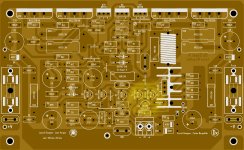
PS can you share some photos?
DX Super A is a full functional and good sounding amplifier.
Thimios
Last edited:
yes i use 10ohm paralel with the inductor. but i only use 2watt. cant find 3watt in my village.
is it 2 watt that drive offset to -20 v ?
is it 2 watt that drive offset to -20 v ?
bagus on my personal Dx Super A's I have 10mV offset on one board and the other one I have 12mV remeber the the boards were design to work on about +43V - 0 - -43V DC
the resistors are already set to that voltage if you use lower voltage than that it might not be enough or better say perfom correctly to that power supply of 22V DC "this is only the way I see" it I might be wrong, also can be other things
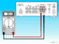
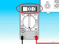
when you say -20V do you mean -20 mV ?
here is what I found I know there are amplifier that can have even lower offset reading but reality is that I let that subject to experts.
How to Measure DC Offset: 5 Steps (with Pictures) - wikiHow
Analyze the result of your reading. The ideal amount of DC offset is 0, which results from a perfectly balanced AC sine wave. In reality, an offset between 0 and 20 mV is very good. An offset between 20 and 50 mV is slightly higher than the ideal range, but the distortion caused will barely be audible. A range from 50 to 100 mV will begin to cause noticeable degradation of the audio quality, while an offset over 100 mV may cause permanent damage to your speakers.
don't mind about the meters the illustrations are wrong 🙂
Regards
Juan
the resistors are already set to that voltage if you use lower voltage than that it might not be enough or better say perfom correctly to that power supply of 22V DC "this is only the way I see" it I might be wrong, also can be other things
when you say -20V do you mean -20 mV ?
here is what I found I know there are amplifier that can have even lower offset reading but reality is that I let that subject to experts.
How to Measure DC Offset: 5 Steps (with Pictures) - wikiHow
Analyze the result of your reading. The ideal amount of DC offset is 0, which results from a perfectly balanced AC sine wave. In reality, an offset between 0 and 20 mV is very good. An offset between 20 and 50 mV is slightly higher than the ideal range, but the distortion caused will barely be audible. A range from 50 to 100 mV will begin to cause noticeable degradation of the audio quality, while an offset over 100 mV may cause permanent damage to your speakers.
don't mind about the meters the illustrations are wrong 🙂
Regards
Juan
Attachments
Last edited:
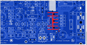
NO,the HEATSINK wired to ground ,not the bd139.mr thimios, why bd139 wired to ground? i used c5200
Bd139 MUST TO BE isolated from heashink(use mica)
2sc5200 is NPN and must to put this in plase of mjl4281
2sa1943 is PNP and must to put this in place of mjl4302.
Do not take care for these 10R ,now it's important to solve this -20V output D.C.
Thimios.
Last edited:
Try GND the heat sink but the Q36 need to be insulated with a mica
all your signal GND are well connected sir ?
Regards
Juan
all your signal GND are well connected sir ?
Regards
Juan
Attachments
Last edited:
On my first boards I use 220nF on the new ones I use 100nF honestly I did not see any different in sound or other changes Mr bagus
now that I'm thinking if you have -20V of offset probably one of the TO-92 are defective maybe you install with out notice counterfeit ones
it does happen a lot.
Juan
now that I'm thinking if you have -20V of offset probably one of the TO-92 are defective maybe you install with out notice counterfeit ones
it does happen a lot.
Juan
Last edited:
but its ok on dx mkII.. ok for sure i'll put it out for checking.
thx you mr vargas
the wierd thing is when i turn it off, in the end off current is begin to + and its sound just 1 second
thx you mr vargas
the wierd thing is when i turn it off, in the end off current is begin to + and its sound just 1 second
Last edited:
sorry i dont have the camera. my bc546 n bc556 kind of strange. its pin same as 2n5401 n 2n5551. i revert all and start all over again, n bias is set. but offset back to 12volt not mv again. n input have huge current amount 1,5v. hhhhh... this must be the cause.
thx you all for helping me.
thx you all for helping me.
Shouts Fakes !!........ my bc546 n bc556 kind of strange. its pin same as 2n5401 n 2n5551................
BC and E line are cbe
2N are ebc
2S and To220, 247, 264, To3p are bce
To126 are ecb
There are a few exceptions.
L versions of BC are ecb
BTW,
I had to read the table printed inside my datasheet folder.
Use what you have on hand, but be careful putting transistor with right position .thx mr andrew.
due rare of the bc546 can i use 2n5401/2n5551 but keep bd139/bd140 ?
Mr bagus I guess you can but remember you have to rotated them at 180 degrees because legs has different pin orientations I mean if you don't have BC546/56 on hand at least with those 2N5401/2N5551 can get you going but keep BD139 and BD140 if you know they are not counterfeit you should be good, what brand you use ? I usually use On semiconductors brand
Regards
Juan
Regards
Juan
Attachments
yes mr vargas. i put 2n5401/5551 and turn it on...
damn... it's on and a LIVE....!!!!
bass so good with compact mid. I LOVE IT...
thank you mr Vargas, mr Andrew, mr Thimios and speccially to author mr Carlos.
thank you very much. you give me a lovely amp
damn... it's on and a LIVE....!!!!
bass so good with compact mid. I LOVE IT...
thank you mr Vargas, mr Andrew, mr Thimios and speccially to author mr Carlos.
thank you very much. you give me a lovely amp
- Home
- Amplifiers
- Solid State
- Dx Blame ST together Dx Super A