The History of Dx Blame ST operating as a subwoofer amplifier started here
Enjoy....videos are fun too!
YouTube - Durabrand cheap home theater introduction - Chapter 1
YouTube - Durabrand cheap home theater - Chapter 2
YouTube - Durabrand cheap home theater - Chapter 3
YouTube - Durabrand cheap home theater - Final Chapter
regards,
Carlos
Enjoy....videos are fun too!
YouTube - Durabrand cheap home theater introduction - Chapter 1
YouTube - Durabrand cheap home theater - Chapter 2
YouTube - Durabrand cheap home theater - Chapter 3
YouTube - Durabrand cheap home theater - Final Chapter
regards,
Carlos
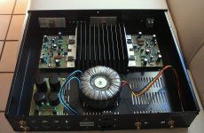
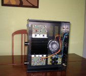
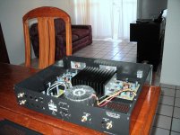
A few of photos of my completed BlameST. Based on Rudi's boards (which are a dream to work with.)
I am still trying with different pre-amp and speaker combinations but I really enjoy what I hear.
Thank you Carlos.
Ryan
Good work RKH. That hula girl really sets off that amplifier.
Regard
niss_man
I have perceived the hula girl too...nice...very nice
I have visited Hawai.... beautifull place.... the most beautifull place in earth.
About amplifiers..... build an amplifier boys...do not know which one to build?.... so, build this one!
regards,
Carlos
I have visited Hawai.... beautifull place.... the most beautifull place in earth.
About amplifiers..... build an amplifier boys...do not know which one to build?.... so, build this one!
regards,
Carlos
Attachments


Dx amplifier really rocks!
Check this by yourself...build and come here to say if uncle charlie is right or wrong:
YouTube - Dx Blame ST - Brazilian group buy green boards
regards,
Carlos
Check this by yourself...build and come here to say if uncle charlie is right or wrong:
YouTube - Dx Blame ST - Brazilian group buy green boards
regards,
Carlos
Uncle Charlie will be watching Youtube with Brazilian Carnival
Live to the whole world....please connect your Dx Blame, crank the volume up and enjoy the rithm played by the Excellence in amplifiers...you're invited, then type:
YouTube - carnaval's Channel
regards,
Carlos
Live to the whole world....please connect your Dx Blame, crank the volume up and enjoy the rithm played by the Excellence in amplifiers...you're invited, then type:
YouTube - carnaval's Channel
regards,
Carlos
Attachments
Last edited:
As every year I go to a DIY day in Holland.This year I'm planning to introduce my Blame ST over there.Carlos, can you give me all the information I need like what kind of toplogy(bootstrap....etc.) that's used and the specifacation etc.?
It is a conventional, or generic amplifier based in Douglas Self Blameless
It uses CCS feeding the differential amplifier and does not use CCS feeding the VAS (Voltage amplifier stage)...in place of CCS was installed the old and good bootstrapp inspired in Aksa 55 amplifier (from Aspen Amplifiers, from Hugh Dean).
The output is a standard emitter follower using a suckout condenser.
The amplifier has rails diodes avoiding input supply voltage discharge and resistances to separate, or insulate a little bit the input voltage against the voltage losses we may have in the main power supply... avoiding modulations in the earlier stages.
It uses an enhanced dual transistor VAS, "A là Self" that really increases sonics a lot, and it was "tuned" to different currents compared to Blameless original circuit.... there are some small other modifications in order to tune the amplifier for sonics...made in a try an error basis, aided by an scope and a simulator...the prototype was tweaked having a blameless as reference and also compared with Aksa amplifier (modern ones), also JLH and HRII, and Precision 1 and DHR Turbo and a secret one from PASS..... this way i tweaked to make it sound "the way i like"...and this is "the best wide world amplifier ever made" to my ears..my personnal evaluation and opinion..confirmed by hundreds.
The input sensitivity is adjustable and preset is around 750 milivolts peak input to drive the amplifier to full power swing, which is 20 volts rms over 4 or over 8 ohms..means 100 or 50 watts rms with 35 volts, 180 watts DC supply (to each channel)
The input impedance is 10K
Audio bandwith is from 5 to 100 kilohertz -3dB curve
Power consumption is around 180 watts... class AB amplifier...iddle current from 50 to 100 miliamperes..supply drain is 2.5 amperes each rail...output fuse is 5A each channel
The amplifier can operate, without any modifications, from 12 plus 12 volts till 42 plus 42 volts DC.
Damping.... better than you may need (alike Rolls Royce use to say.... enougth!
Distortion is 0.003% THD... full power...and harmonics distribution is just awsome.
You can invite everyone in your demonstration, to a comparison...same power..same speaker...you gonna eat several in the breakfast...and tell me the brand name and model if someone was good enougth to beat this amplifier...i will immediattelly search to build too, to check this..and this is reality..i will produce a Dx inspired of the one have beated the Dx Blame amplifier...i really doubt you will find the one..as i am searching this last 51 years and i could not....
Well..... Tubes can beat it.... easy!
Also do not let them to plug preamplifiers.... the main advantage Dx products have is that does not have preamplifiers to mess the whole thing (sometimes they do not mess).... plug it direct or you will reduce the advantage we have in advance... others has a lot of messing circuits...Dx goes direct.... easy trick...obvious advantage.
This amplifier is excelent in audio performance, almost magic in sonics, but keeping the original schematic, that was tuned by ears...if someone, searching for more reliability, replace Q6 emitter resistance by a 1K unit, will loose audio quality...but will gain reliability.... the 220 ohms was the best option for sonics, tuned carefully in a try and error basis...a hard work to do that.... a lot of sweat doing that for days long...no way to sound better than using 220 ohms there..... to increase reliability, use bigger transistor there, as Q6, as BD139 for instance...heatsinks to drivers and VAS (both) is very interesting too.
regards,
Carlos
Last edited:
I am really looking forward building this Amp (supercharged), will be my 1st one though. I will be building 2 monoblocks and for now I will use my receiver as pre-amp, well switch actually.
All materials for the amps ordered. Softstarts, speaker protections and filterbanks are finished! 🙂
I do have one question; There are 2 torroids with 2x 38V secundaries collecting dust here so I want to use them. The only thing is that they are massive, 625VA ones.
If I am remembering correctly it was mentioned somewhere not to use "too big ones" but I cannot finf that post anymore.
So could someone enlighten me? 😱
Thanks in advance!
It is not very safe..with a huge transformer alike that, feeding one channel
You will be able to produce more than 400 watts rms..... this is a little bit dangerous...you should try to use 8 ohms or a "safe" 4 ohms speaker...this amplifier is not good for 2 ohms loads...this may destroy output transistors.
It is rated to 100/200 watts...but the real problem is that it can put much more than that ... 150 and 300 watts is not difficult in 8 and 4 ohms loads...and this may happens if power transformer is strong enougth to feed current to the power amplifier without too much voltage drop..and this is exactly your case dear dilirium.
You may perceive that 300 watts is already dangerous to 2 pairs to dissipate...imagine if your speaker impedance drops to lower than the nominal 4 ohms..and this happens when we use passive crossovers..not only because speaker characteristics, but also and mainly because criminal crossovers.... you may have 2.5 ohms in a 4 ohms speaker...... and having this sittuation...under that condition...if a huge transformer will be feeding your power amplifier..then you will start to invite bad luck to your life....output may burn..and you will be frustrated and wasting your money.
If you know how to check your speakers... and IF THEY are 4 ohms...then check it for impedance.
An easy trick is to install a power variable resistor... we call here in brazil "reostato".....it is a wire potentiometer to high power electrical controls... then you can check your real impedance installing it in series..then you generate tones with a tone generator and send this signal to a power amplifier.... low power is good...not needed to go higher than 5 watts rms... then you will have that potentiometer installed in series with your speaker..... producing a voltage divider..... one resistance is known..the potentiometer..the other is not very well known..the speaker impedance that will depend on your test frequency..... preset in 4 ohms your potentiomenter and install two AC meters... one measuring voltage drop over the potentiometer and the other measuring the voltage drop measurable into the speaker terminals..... the voltage divider rule is that when resistance is the same.... the voltage will be exactly divided by two..this way you can check, having patience, your speaker in several frequencies and adjusting potentiometer to divide voltage in two exactly equal parts..then you will be absolutelly sure about the reaimpedance or the speaker under test......you know..if you divide by two and potentiometer is adjusted in 2.5 ohms..then this is your speaker impedance..there are other methods but needs instruments..this you can make with a signal generator with variable frequency and two AC meters or Multimeters (yellow cheap ones do the job).
You can also increase your quantity of output transistor or produce a current limiting using series resistances in between your power supply and your power amplifier..because this will force voltage drop protecting and avoiding the power amplifier to face excessive power.... i do think 1 ohms to each rail may help...the problem is that it will be very hot..you gonna need big resistance..so..this is not really practical... increasing the output transistors pairs will be better...and never use 4 ohms speakers..if they show you big dips of impedance...then... having a difficult speaker, will be better to avoid to use it.
The amplifier was made to save money..only two pairs used..but i told folks to use 350 watts transformer to each channel..and never more than 350 watts transformer....was made this way to protect your amplifier against troubles..... try to use a single transformer..then things will be controlled.
Was suggested 350 watts exactly to save money in the transformer size...to save money about the output transistors quantity and to make this amplifier reliable...going above this power in your transformer you will inviting the demon to make a visit to you.
Do not forget to use big transistors in both VAS positions..... MJE15XXX series...both using heatsinks... this way you will be free to overdrive your power amplifier without the risk to face problems with Q6 that burned with 2 percent of our builders when they overdrive their unit input.
regards,
Carlos
Attachments
Last edited:
Thank you for your clear answer! Since this is my first Amp I will keep it on the safe side and buy some smaller transformers. I do not think it will be smart to fiddle around with the different components at this moment since I have no practical experience building Amps and I might not know exactly what I am doing yet 🙄
Parts are ordered according the BOM on the website.
My speakers' lowest impedance is 3,4 Ohms according manufacturer (Dali) but I do not know how true this given value is.
Thanks again!
Parts are ordered according the BOM on the website.
My speakers' lowest impedance is 3,4 Ohms according manufacturer (Dali) but I do not know how true this given value is.
Thanks again!
Dali is a wonderfull speaker manufacturer
I am glad my amplifier will play together a Dali.
To the ones does not know Dali...here you have a video:
http://www.youtube.com/watch?v=-39OqH4C2P8
regards,
Carlos
I am glad my amplifier will play together a Dali.
To the ones does not know Dali...here you have a video:
http://www.youtube.com/watch?v=-39OqH4C2P8
regards,
Carlos
This is guaranteed..you will be happy with it.
But never forget, as a safety rule, to use fuses in series with your speakers...or a speaker protector circuit.... for the Supercharged use 4A to 8 ohms speaker and 8A to 4 ohms speaker.
To the Dx Blame ST, then use 2.5A when facing 8 ohms speakers and 5 amperes to 4 ohms speakers..... or a protective circuit using relays, or a crowbar circuit using SCR.
regards,
Carlos
Last edited:
Enjoy brazilian carnival live from youtube fellows
Equalize reproduction following loudness contour...cranck computer audio board volume one third up and plug a Dx Blame...this one full power, to listen the best of sonics.
regards,
Carlos
Equalize reproduction following loudness contour...cranck computer audio board volume one third up and plug a Dx Blame...this one full power, to listen the best of sonics.
regards,
Carlos
Attachments
Last edited:
I have just received a pair of Rudi's pcbs to build this amp, but have a question:
Where should the speaker return be connected? To the amp pcb main 0V connection (where is says "GND-SPK") or to the power ground on the power supply pcb?
I will be building a dual mono amp.
Where should the speaker return be connected? To the amp pcb main 0V connection (where is says "GND-SPK") or to the power ground on the power supply pcb?
I will be building a dual mono amp.
I use to fix the transformer center tap..the secondary central wire
goes attached to ground, using bolts and nuts...or solder...so..chassis connected to main ground...that will be the supply ground, also the power amplifier ground.... you should pick your speaker wire at this central ground..the earth connection..the star ground.
But also you can keep your chassis insulated from circuit ground if you prefer..maybe you have grounding pin in your mains connection..i do not know how is your standards to home outlet of mains plugs.
This way..the transformer center tap will not go to chassis...will go to the supply board and also to the power amplifier board ... and then you can pick you audio ground wire into the transformer center tap too.
If you decide to use input volume.... a potentiometer...a good idea is to ground it....to avoid noise pick up (hum from mains)...in this case, as you see..your potentiometer metalic case will make the "grounding"..connecting your amplifier input ground to the chassis.... doing this way you will be deactivating the lifted low noise ground (10 ohms lift resistance).
I do think it is a good idea to connect transformer secondary center tap to ground...this way you potentiometer will be grounded and you will not have the need to run a wire from audio input ground to the chassis ground....not deactivating your lifted ground.
I hope i was clear about that... people use to call this star ground.... a central point where all ground wires goes... avoiding ground loop noises.
I do not know how Rudi made..as seems to me he is using a wooden case to his power amplifier.
regards,
Carlos
Hi Carlos,
Yes I believe you are correct. This is normally the way I would connect the ground(s):
Chassis hard connected to mains earth - for safety
Dual mono with power star at the lowest impedance point i.e. between the last pair of smoothing caps on the PSU board. Speaker return goes to this point.
However....
I have one concern with the DX amp and that is the 470 - 1KuF on board decoupling caps. Let's consider the situation after a large transient when maybe the local rail has dipped by 2V, this cap will recharge from the main PSU caps and the rectifer (during it's conduction period) and put up to e.g. 20A peak of return (i.e. ~2V/100mOhm) charging current through the wire that connects the PSU 0V to the Amp 0V. Any voltage drop across this wire (maybe 0.1V i.e. 20A X 5 mOhm) will be between the input ground to the amp and the speaker return. This is a common mode signal because it also "moves" the input 0V by the same amount (ignoring the 2nd order effects of the recharging of the front end decoupling caps through the 33R resistors and their effect on the 0V potential).
Maybe this common mode signal does not matter, but my concern is that recharging currents are NOT musically related to the signal and therefore any errors caused by them could result in smearing of the sound.
Anyway, I think the solution is to get the PS very close to the input of the amp and connect the two with a thick wire.
I understood your point
Surge protection is a very good idea....Rodd Elliot has a nice one.
regards,
Carlos
Surge protection is a very good idea....Rodd Elliot has a nice one.
regards,
Carlos
- Status
- Not open for further replies.
- Home
- Amplifiers
- Solid State
- Dx Blame ST - Builder's thread - post pictures, reviews and comments here please.