FAKE CMJE 15030
I've done a HFE measurement of the FAKE CMJE 15030 ...(99)
And a measurement of the original MJE 15030 ...(52)
A picture says more than thousand words.
Can someone tell me what can cause this difference to the amplifier?
Regards,
Rudy
I've done a HFE measurement of the FAKE CMJE 15030 ...(99)
And a measurement of the original MJE 15030 ...(52)
A picture says more than thousand words.
Can someone tell me what can cause this difference to the amplifier?
Regards,
Rudy
Attachments
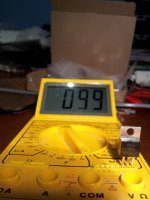
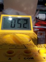
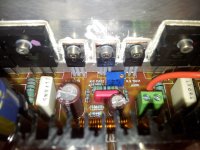
The cmje has higher hfe because it has smaller die inside which would not be able to sustain SOA figures if used as drivers. The mje figures correspond well with those of datasheets. What position are those cmje in??
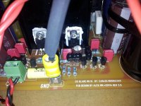
The CMJ 15030 put on the place of the small heatsinks.
The CMJ 15030 that I solder out today, I measure HFE 122
Regards,
Rudy
The CMJ 15030 that I solder out today, I measure HFE 122
Regards,
Rudy
Have now tested, and now I measure 1 millivolt from emitter resistor.
The 100R resistor I measure 4,27 volts.
And the 60 Watt light bulb tester glows only when I switch on the power supply, after 3 seconds glows the lamp no more.
Regards,
Rudy
The 100R resistor I measure 4,27 volts.
And the 60 Watt light bulb tester glows only when I switch on the power supply, after 3 seconds glows the lamp no more.
Regards,
Rudy
Last edited:
Sorry BMW850 im not familiar with this amps layout but if youre using them as vas transistors they should work without problems, theres much less current flowing there although to say what the effects might be would be pure speculation as we dont know exactly what the fakers put into that piece of plastic.
Rudy, this looks good.
So you have a quiescent current of about 42mA.
The bulb tester will only light in the first second(s): during the time of the inrush-current and the time it takes to charge the big reservoir caps.
The bulb-tester will not light, when a very small load of only 42mA is drawn.
Find out the next steps: how to correctly adjust the quiescent current.
Best regards - Rudi
I cannot Change the bulb to a higher wattage because I don’t have higher one, and now I can power up directly from the mains I suppose?
And measure the same things again and put the amplifier on about 1 hour and feel if something get warm.
If not, then I put in de fuse and measure again and trim the bias to 1 millivolt.
After that, I short the input signal hot to signal ground.
Measure the output offset at the speaker terminals.
Measure the output noise at the speaker terminals.
Power off. Let the amp cool a bit.
Regards,
Rudy
Rudy,
what did Carlos tell you about the adjustment of this AMP?
Is the quiescent current of 42mA (voltage drop of 4.2V over 100 Ohm resistor) the value that Carlos recommends?
Rudi
what did Carlos tell you about the adjustment of this AMP?
Is the quiescent current of 42mA (voltage drop of 4.2V over 100 Ohm resistor) the value that Carlos recommends?
Rudi
better to use the resistor and to measure the voltage drop over it, into it's terminals, measuring DC voltage..... then, let's say your amplifier is fine..you gonna measure from 4.7 to 8.0 Dc volts.
I measure 1 millivolt over the emitter resistor.
I measuring 4.7 volts over 100R resistor, that is good.
Regards,
Rudy
Last edited:
Rudy, the voltage you are measuring across the "fuse-resistor" depends on the value of this resistor.
As I understand it, Carlos recommends a quisecent current of 100mA.
If you use a 47 Ohm, then your multimeter will read 4.7V; if you use a 100 Ohm resistor, your multimeter will read 10V.
Please check Carlos' recommendation once more.
Best regards - Rudi
As I understand it, Carlos recommends a quisecent current of 100mA.
If you use a 47 Ohm, then your multimeter will read 4.7V; if you use a 100 Ohm resistor, your multimeter will read 10V.
Please check Carlos' recommendation once more.
Best regards - Rudi
I short the input signal hot to signal ground.
Everyting is good, emitter resistor I measure 1 milivolt constant.
@ Rudi, I measure over 100 ohm resistor 4,7 volt.
And I check Carlos recommendation 😉
Regards,
Rudy
Everyting is good, emitter resistor I measure 1 milivolt constant.
@ Rudi, I measure over 100 ohm resistor 4,7 volt.
And I check Carlos recommendation 😉
Regards,
Rudy
Last edited:
I short the input signal hot to signal ground, and I measure 19,20 volt DC output offset at the speaker terminals.What is the output offset in mVdc?
What is the output noise in mVac?
Sorry you or anybody else explain to me how I measure that?
I short the input signal hot to signal ground, I measure between 1,5 and 3,2 mV AC output at the speaker terminals, it goes up and down.
Regards,
Rudy
Last edited:
I forgot to mention. I power up directly from the mains, and I have the fuse in there.
Tomorrow evening I go further, go to sleep now early day tomorrow.
I short the input signal hot to signal ground, and I measure 19,20 volt DC output offset at the speaker terminals
Let me know where are the errors
Regards,
Rudy
Tomorrow evening I go further, go to sleep now early day tomorrow.
I short the input signal hot to signal ground, and I measure 19,20 volt DC output offset at the speaker terminals
Let me know where are the errors
Regards,
Rudy
Last edited:
I short the input signal hot to signal ground, and I measure 19,20 volt DC output offset at the speaker terminals..............
I short the input signal hot to signal ground, I measure between 1,5 and 3,2 mV AC output at the speaker terminals, it goes up and down
You are being foolhardy.I forgot to mention. I power up directly from the mains, and I have the fuse in there.
Why are you powering up direct on line?
The 19Vdc output offset shows there is a wiring error.
The variable 1.5mVac to 3.2mVac could be showing noise or oscillation or hum at the output. But you must sort the output offset first and any oscillation if it exists, before you can be sure that the mVac reading is noise.
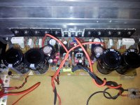
I have all mounted components as described on print screen, hopefully there are no errors on print screen.
All parts measured and sorted before and when I took in the components for soldering, again as first measure the resistors.
Well that I have been reckless, the output offset mVdc and the output noise in mVac I forgot to measure that yes that was stupid, all the other measures good
The GND I use as the minus for the speaker output (out the +) and the other 3 wires (+60v -60v GND) are good connected otherwise we have a lot of smoke.
I know it’s difficult to tell what’s wrong from a distance, but where shall I search the error first.
Regards,
Rudy
Last edited:
Rudy,
do all legs of all transistors that you have mounted vertically, show infinite resistance (MOhm scale on your DMM) in respect to the heatsink?
Rudi
do all legs of all transistors that you have mounted vertically, show infinite resistance (MOhm scale on your DMM) in respect to the heatsink?
Rudi

- Status
- Not open for further replies.
- Home
- Amplifiers
- Solid State
- Dx Blame MKIII-Hx - Builder's thread