I prefer a very low wattage resistor.
If there is over current I want it to smoke and tell me quickly that something needs to be turned off or I want it to blow if I can't turn it off quick enough.
Yes, I know it's a b.... nuisance to solder in a new one each time.
The alternative, proposed by quite a few, is a high wattage resistor that can pass over current for quite a time without needing to be replaced.
The answer you want is anywhere from 250mW to 10W. Your testing philosophy will determine which end of that range you prefer to aim towards.
I certainly can't tell you.
I also believe that no one else can tell you.
I prefer a very low wattage resistor.
If there is over current I want it to smoke and tell me quickly that something needs to be turned off or I want it to blow if I can't turn it off quick enough.
Yes, I know it's a b.... nuisance to solder in a new one each time.
But a fuse does exactly the same, what is the usefulness of these 100R resistor
Now if I start with a 4 Amps fuse.
Regards,
Rudy
If the fuse is set to pass speaker currents without nuisance blowing, then what will the fuse/s pass to the front end amplifier when the output bias is initially set to zero amperes?
Oh My Goodness,,My maid had a daughter that looked like all 3 of them put together.😛😛😛 What a fool I was to just do my work and forget the beauty around me😡Oh well It,s ok I,ll just go my merry little way and be happy with what I have,,I have My dog and my little Evette These tmo really love Poppy. This is worth more than all my transistors and tubes I have.
Keep Sending me your warm feeling I feel better already. PS why don,t I have those circuit boards? And Would you like 2000 lbs of ice? This will cool you off. Evette
Easy joe, them batteries not strong anymore ..........🙂
New layout check it out Carlos.
Nice progress meanman...

Dear BMW850, the resistor, the protective one, can be a 5 watts unit
or a 10 watts unit or even more..... this depends on your trimpot settings, your adjustment and your bias transistor gain.
If you start your amplifier with your trimpot (1K) adjusted to the maximum, your current will be around 62 miliamperes or a little bit less.... then 5 watts will be good enough.
If you start your amplifier with your trimpot adjusted to minimum..then your current can be huge...and maybe 10 watts will be small.
The idea of this resistors BMW, is to avoid fuses burning if your amplifier is misadjusted or if it has wrong assembly... defects, failures, mistakes, missing parts and shorts... then all current will be over this resistor that will limit the current.
Imagine your amplifier is a short... a very low resistance due to transistor failures, shorts, mistakes and so on.... then it will represent zero ohms.... this way the supply 64 volts will be crossing it and this will limit the current.... by ohms law you divide the voltage by the resistance and then you have current.... 64 divided by 100 will result in 0.64A or 640 miliamperes.... this voltage multiplied (power is voltage multiplied by current) by 64 will result in 64 watts...then your 10 watts resistor will smoke.... only a 50 watts unit will be good to this position when you have short.
The idea is not to have shorts...then the power there will be small...if something is wrong the resistor will overheat and you gonna have time to switch your supply power off...for short time measurements a 10 watts resistor can face 10 times more power, but for a second or two...not for longer time....you should be fast to switch off.
Using a fuse you will have it burned...and with fuse you cannot measure the voltage drop into the fuse terminals...the resistance there is zero and voltage drop will not be easy to be measured, as a 1/1000 of ohm resistance should be there..... you cannot know your current, your total current unless you plug two amp meter in series with your supply rails.
If you plug an amp meter and your amplifier is in short..then the current will be huge and copper tracks will melt.... when using the resistor, what gonna melt is the resistor and not your pcboard copper tracks...better to be resistor, or fuses.
Plugging amp meter in series is a problem..if your amp meter fuse opens..then your output voltage will raise to rail voltage.... having speaker as a load it will have it's coil burned...not a good idea to use two amp meters...better to use the resistor and to measure the voltage drop over it, into it's terminals, measuring DC voltage..... then, let's say your amplifier is fine..you gonna measure from 4.7 to 8.0 Dc volts.
I hope this was clear enough....it remained any doubt..please, ask again and i will try to clarify once more.... or twice more...or three times more...i can produce video, or two videos...do not be ashamed to ask... a shame is not to ask.
Start your amplifier with your bias trimpot adjusted into the maximum resistance.... 1000 ohms
regards,
Carlos
Last edited:
Andrew and Carlos thanks for the information, I can learn thinks only by questions.
Hope this week have all components here, so I can test the amplifier.
I am so curious how this amplifier sounds (after a long stress test) on my big speakers, on this website you all can see the speaker how it looks inside: http://www.lark-bg.com/sp/acrrp400isostatic.html
Regards,
Rudy
Hope this week have all components here, so I can test the amplifier.
I am so curious how this amplifier sounds (after a long stress test) on my big speakers, on this website you all can see the speaker how it looks inside: http://www.lark-bg.com/sp/acrrp400isostatic.html
Regards,
Rudy
Last edited:
Your going to love it. Sit back with a glass of wine or whisky light up your cigar and feel your in heaven. Good Luck Sir Rudy.
Yes...i am sure you gonna love it
Good speakers you have...if your acoustic environment is also good...if your audio source is good..then you will feel strong emotions.
Prepare yourself to feel the touch of the divine.... the song from the paradise... place a camera in front of you...switch the recording button on... cranck the volume at 75 percent... then register for the sweet moment that you gonna be dancing!
You know.... i am already travelling to the future and watching you...do not forget to switch your lights on and to open your windows..this damn camera needs a tripot.... this shoe you are wearing is not that good to dance...i know it is cold outside..but your soul gonna be so hot that you will not feel all that cold.
Why test it at night?
Satisfaction Guaranteed!
regards,
Carlos
Last edited:
Two complementary videos about bias adjustment and protective resistor
uploaded to youtube.... here you have links:
Audio Amp. bias adj & series protective resistor - part 1 - YouTube
http://www.youtube.com/watch?v=Tua4d2tWcwk
If something is not clear...then let me know.
regards,
Carlos
uploaded to youtube.... here you have links:
Audio Amp. bias adj & series protective resistor - part 1 - YouTube
http://www.youtube.com/watch?v=Tua4d2tWcwk
If something is not clear...then let me know.
regards,
Carlos
P.S. How are you doing with your amps? Need anything to help you ? Joe/Evette
Yes, i will contact you , question on trannies and working on the PSU for the vas stage and had a couple things i wanted to bounce off you .
Regards,
Start your amplifier with your bias trimpot adjusted into the maximum resistance.... 1000 ohms
regards,
Carlos
Hi Carlos,
If I use your method, I must make sure I have a heavy lamp (100watt?) in the bulb tester?
And if I use Anndrew's method I start "for example" with a 30 watt bulb.
Understanding the trimmer resistor
what you have calculated is basically correct.
The big difference between your assumptions and the real circuit is that the 1355r is not a resistor, but a complex combination of resistors and semiconductors.
The other assumption that does not hold, is that the +ve and -ve currents do not need to be equal. If they were then the ground would not pass any quiescent (no signal) current.
If you apply the correct supply voltage to the amplifier when the output bias is turned down to minimum then you can start setting up your amplifier.
Using Carlos' method.
Power down and insert a 100r in place of the +ve rail fuse. This 100r could be soldered permanently across the fuse holder terminals so that all you need to do to set up the amp is remove the fuse.
Power up using the bulb tester to prevent damage if something has been changed by accident.
Check the bulb is off or has a VERY DIM GLOW.
Measure the voltage across the power supply terminals.
Measure the voltage drop across that test/set-up resistor.
Now slowly increase the bias voltage across the Vbe multiplier. Use small increments and measure the bias voltage, measure the test resistor voltage.
Continue increasing the bias voltage. You will probably find that the bulb will become increasingly bright. Do not change the bias setting. Change the bulb to a higher wattage, or if you are really sure you won't make a mistake power up directly from the mains.
Recheck the bias voltage and the test resistor voltages. They will have changed since moving from the low value bulb wattage.
Why have the test voltage changed, I only removed the bulb tester. They change usually increase because the Power supply voltage will have risen.
Now start increasing the bias voltage checking both those test points. Keep increasing until you reach the final setting given by Carlos. Check device temperatures check for burning or overheating smells. Check device temperatures. Wait a while and recheck device temperatures.
When the amp reaches it's final operating temperature, 30 to 60 minutes say, recheck the test voltages. Readjust the setting is necessary. replace the fuse. You have now changed the PSU voltage. The test voltages will have changed, but you can't measure them, because you have bypassed the 100r resistor with a fuse.
Job done.
BUT DO NOT connect your speaker yet.
Short the input signal hot to signal ground. measure the output offset at the speaker terminals. Measure the output noise at the speaker terminals. Power off. Let the amp cool a bit.
Power up and recheck the output AC and DC voltages. Leave the amp running with shorted input for many hours with the occasional OFF/ON to stress the components. When you are sure that the amplifier is behaving itself, then it is time to connect a cheap speaker.
Listen for any hum.
Power OFF. remove short from input. Power ON. Is the speaker still working? Can you hear any noise? Is the cone still at it's centre travel position? Measure the AC & DC voltages at the speaker terminals. Are they similar to those from before.
Power OFF, connect an audio source. Power ON. Recheck your voltages. Is the speaker still OK?
Now listen to some quiet music. Does it sound "clean".
Job really done.
OFF, connect your real speakers, ON, enjoy.
Regards,
Rudy
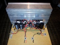
One Dx Blame MKIII-Hx amplifier is ready.
One Dx Blame MKIII-Hx amplifier is ready.
Tomorrow I test the amplifier with my existing power supply, 3 screws and the amplifier is connected.
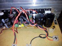
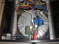
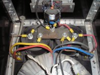
This is my Zappulse 2.3SE amplifier monoblock 1 Torroid 2000VA 2 x 42 volt, not look at the dust, this is an old picture 😉
The 2 elco's are Mundorf 47000uF 80V MLytic High Current, I supose that 94.000uF is enough.
This is a homemade cabinet, front is 10 mm thick and side panels and bottom 6 mm thick.
Build another cabinet, because this cabinet is to small for the Dx Blame MKIII-Hx amplifier 😉
Regards,
Rudy
One Dx Blame MKIII-Hx amplifier is ready.
Tomorrow I test the amplifier with my existing power supply, 3 screws and the amplifier is connected.
This is my Zappulse 2.3SE amplifier monoblock 1 Torroid 2000VA 2 x 42 volt, not look at the dust, this is an old picture 😉
The 2 elco's are Mundorf 47000uF 80V MLytic High Current, I supose that 94.000uF is enough.
This is a homemade cabinet, front is 10 mm thick and side panels and bottom 6 mm thick.
Build another cabinet, because this cabinet is to small for the Dx Blame MKIII-Hx amplifier 😉
Regards,
Rudy
Attachments
-
 20120114_173859.jpg410.7 KB · Views: 396
 -
 20120114_174041.jpg386.7 KB · Views: 374
 -
 20120114_174141.jpg407.3 KB · Views: 357
 -
 20120114_174446.jpg382.9 KB · Views: 334
 -
 20120114_174618.jpg446.5 KB · Views: 323
 -
 P1010154.jpg91.2 KB · Views: 168
 -
 P1010155.jpg99.9 KB · Views: 180
 -
 P1010156.jpg99.1 KB · Views: 161
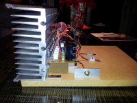
Light Bulb tester for DX Blame MKIII - HX
Hello,
I have created a video on youtube of my Light Bulb tester.
The 25-watt light bulb tester is tested after a small amplifier.
Is 25 watt bulb enough for first testing?
Light bulb tester for DX Blame MKIII - HX - YouTube
Regards,
Rudy
Hello,
I have created a video on youtube of my Light Bulb tester.
The 25-watt light bulb tester is tested after a small amplifier.
Is 25 watt bulb enough for first testing?
Light bulb tester for DX Blame MKIII - HX - YouTube
Regards,
Rudy
Another video in artificial light in the evening, I think that the quality of the video is better by daylight, you can hear that I am a cold😉
DX Blame MKIII - HX - YouTube
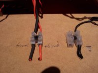
It's all a little messy connected but for testing it is not so important.
Thanks Evette, I need a little luck 😉
Regards,
Rudy
p.s. Camera is the Samsung Galaxy S2
DX Blame MKIII - HX - YouTube
It's all a little messy connected but for testing it is not so important.
Thanks Evette, I need a little luck 😉
Regards,
Rudy
p.s. Camera is the Samsung Galaxy S2
Last edited:
Nice Work !
Rudy, An Excellent video. Your work looks great. After it gets burned in I'd like to hear your opinion on the sound. I believe you built several amps to compare to..... Anyway, I appreciate the time you took show & help out other DIY members..... turn up the music!
Rudy, An Excellent video. Your work looks great. After it gets burned in I'd like to hear your opinion on the sound. I believe you built several amps to compare to..... Anyway, I appreciate the time you took show & help out other DIY members..... turn up the music!
- Status
- Not open for further replies.
- Home
- Amplifiers
- Solid State
- Dx Blame MKIII-Hx - Builder's thread