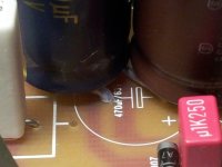
Oh!...that's terrible Byron.... connected to negative lead?
Not a good choice the condenser factory made..... unbelievable error from the industry..these can must be insulated from the condenser poles.... yeah.... retarded brain solution... a surprise to me these things...i have never found a unit like that.
Well...i am glad you have found the problem...now think in a solution to keep your lovely condensers..they look good and i know you love them...you may find the way..insulating it with rubber, wood, or any other insulating material...not to loose them.
regards,
Carlos
Attachments
Last edited:
On reading Byron's warning I immediately went upstairs and checked my studded Sikorels.
They too have stud and -ve connected.
S+M
SIKOREL 105
B41570-A9108-q
They too have stud and -ve connected.
S+M
SIKOREL 105
B41570-A9108-q
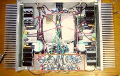
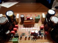
The components that you are seeing now on the board are soldered now, 1 amplifier is now almost finished I wait with the other board, first to test this one.
Now I make the light-bulb tester, I have all the components.
The small heat sinks are on the way and the M3 machine tap is also ordered for tapping into the large heat sinks.
On the photo you can see how I have solved the 220uF 100 volts caps issue
The capacitor legs, I scrolled Teflon tube.
Regards,
Rudy
p.s. I order also 2x Roederstein MKT1813 1,0uF 100V
Attachments
Last edited:
850,
How are you stabilizing/supporting those caps, a dab of silicone underneath ...?
Yes, and a tire wrap.
Regards,
Rudy
Edit: pictures are made with mobile phone
Attachments

Last edited:
Similarly, the two pairs of big caps will be stronger and stiffer if you tie wrap each of the pairs.
One 4leg mounting is far better than the sum of two 2leg mountings. Especially so when the legs are farther apart.
One 4leg mounting is far better than the sum of two 2leg mountings. Especially so when the legs are farther apart.
Similarly, the two pairs of big caps will be stronger and stiffer if you tie wrap each of the pairs.
One 4leg mounting is far better than the sum of two 2leg mountings. Especially so when the legs are farther apart.
You have a way with words, Andrew😉 Thank goodness mostly audio engineers / enthusiasts will be reading this!
Regards,
currentflow
For the football fan in you I will explain further.
Take a pair of goalposts at each end of the pitch.
Bring one set to the other end. Mount them solidly in the ground about 3m (10') behind the normal goal posts.
Now tie a rope to the crossbar and find out how much load is required to pull over that one set of 2leg structure.
Now repeat the experiment for the other 2leg structure.
Sum the results from both experiments.
Now a thinking exercise. Tie the cross bars of both the undamaged goal posts together. Now estimate the force required to pull both sets of 2 leg structures over.
It should be roughly double the result from each of the first two experiments.
The two sets of relocated goalposts are are 3m apart and they are ~2.5m high.
Brace the uprights at the ends together with a big X frame 2.5m high by 3m wide.
You now have a 4leg structure. Still 4 connections into the ground still the same upright dimensions.
Now the next thought experiment.
What force applied to the crossbars will be required to pull over the 4leg structure? Will it be less than the sum of the two 2leg structures or the same or more than the sum of the 2leg structures?
Finally, stiffness
Apply a force via the rope that is only half the force necessary to pull over the single 2leg structure.
How far does the cross bar move?
Now apply that same force to the second goal post. How far does it move?
Now apply that sum of two half value forces to the 4leg structure with the X bracing attached.
How far do the goalposts/crossbar move?
Is it less or same or more than for the 2leg structures?
I think if I set that as a topic for an experiment, physical and mental, in a science or technology class for 12year olds, they could give something approaching the correct conclusions.
Tie wrap around a pair of close coupled capacitor cans is the equivalent to adding the bracing to the goalposts.
The +ve and -ve legs of the two capacitors are the equivalent to the bottom ends of the uprights of the goalposts.
Last edited:
For the football fan in you I will explain further.
I don't understand. Is this American football, or European football, a.k.a. soccer?

Currentflow declares United Kingdom and shows a Union Jack.
I suppose that means I mean football.
I suppose that means I mean football.
I don't recall questioning the clarity or accuracy of post #626, but thank you for your list of useful equivalents.
The post put a smile on my face and for that I am grateful.
Regards,
currentflow
BTW, I'm not a football fan.
The post put a smile on my face and for that I am grateful.
Regards,
currentflow
BTW, I'm not a football fan.
I know next to nothing about football, glad i can compensate for it
with my knowledge of basic carpentry in this case 😀
You can apply the same technique to the 2 pairs of large powersupply-caps
by using some hotmelt-glue to link them.
This also has the effect of stiffening the pcb, the pair of ps-caps will act
as a brace.
Btw, i guess i was lucky with my Fischer & Tausche studded caps
10.000uF/63V.
I've seen studded caps in industrial applications mounted on a rail,
why a manufacturer fails to mention the connection from -ve to the housing
in the effin' datasheet is completely beyond me.
Regards,
Klaas
It's not just electronics companies datasheets. I have had a nightmare with a central heating boiler for days now.
It was a choked water filter that doesn't even get a mention in the makers manual other than one line in the servicing section that says it must be cleaned yearly. It would have helped if it was noted on the parts list.
It gives the same symptoms as a choked plate heat exchanger which most folk would have bought and fitted, only to find the problem lies elsewhere. I wonder how many £80 heat exchangers that has sold for them? I have one of them in front of me right now.
John
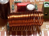
12 mm diameter
Regards,
Rudy
Verzonden vanaf Samsung Galaxy S2
Try 8
I think it's better to have some space between the windings
Last edited:
Air cored inductor calculator
Coil diameter 12 mm
Coil length 25 mm
Number of turns 22
2.268 µH
This is isolated copper wire.
Regards,
Rudy
Coil diameter 12 mm
Coil length 25 mm
Number of turns 22
2.268 µH
This is isolated copper wire.
Regards,
Rudy
Last edited:
- Status
- Not open for further replies.
- Home
- Amplifiers
- Solid State
- Dx Blame MKIII-Hx - Builder's thread