I guess is natural
Cool wow well I didn't know much about editing is just natural for me I guess lol :
Cool wow well I didn't know much about editing is just natural for me I guess lol :
I spent the whole evening tuning some buzzing noise issues... This amp is the only device of my system that's grounded. It created problem when connecting to "floating ground" devices. My biggest problem is when I connected the DVD player to my DAC using the coaxial cable, it gave quite a buzzing sound.
I finally found that the buzzing came from the coaxial video signal from my provider (that goes to the TV set, then my DVD player is connected to the TV, a nice ground loop here). I had to ground that cable both at the entry point in the house and behind the TV receiver. It's all good on that side now.
I know that I've grounded my amp for safety purpose, but why do the consumer integrated amps, TVs and all of this stuff doesn't have a ground? to avoid those loops and save on support? how can all of this be safe and not our DIY project without a ground?
Martin.
Single-Layer Air Coil Calculator
Here you have a Single-Layer Air Coil Calculator:
Pronine Electronics Design - Single-Layer Air Coil Calculator
Regards,
Rudy
Here you have a Single-Layer Air Coil Calculator:
Pronine Electronics Design - Single-Layer Air Coil Calculator
Regards,
Rudy
 OT posts removed as requested.
problems with power supply, any suggestions?
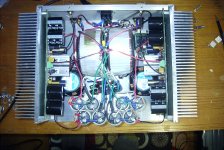
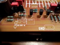
I'm all finished building, meaning everything is put together. (see first picture) Two things are not working right, which may or may not be related.
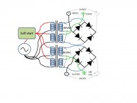
One, is that I'm getting more voltage from one power supply than from the other. I have a dual power supply. Each uses 40-0-40 secondaries. But I'm measuring 43-0-43 on both. That's probably not a big deal, but after rectification I'm getting 110VDC across the positive and negative of one PS, and 161VDC across positive and negative of the other PS. This shouldn't even be possible (86*1.42=122). Furthermore, this voltage is not divided evenly between positive and ground (100VDC) and negative and ground (62.5VDC). I checked every diode (MUR860) and get exactly 0.403 ohms and no conductance in the two directions for all 8 diodes. Note that all these measurements were taken with no load - that is, positive and negative rails were open, so no current was flowing. They were also taken without filter caps in place. I don't know if that effects my measurements. Please see the second picture for a diagram of the PS, without filter caps.
The other problem is that I keep blowing mains fuses (5amp slo-blo) on start-up, even with my soft start. They don't blow as long as I don't have the filter caps hooked up. I don't know if my soft-start is not working properly, or if it is just not "soft" enough. Maybe it needs a larger timing cap?
Any help is greatly appreciated.
I'm all finished building, meaning everything is put together. (see first picture) Two things are not working right, which may or may not be related.
One, is that I'm getting more voltage from one power supply than from the other. I have a dual power supply. Each uses 40-0-40 secondaries. But I'm measuring 43-0-43 on both. That's probably not a big deal, but after rectification I'm getting 110VDC across the positive and negative of one PS, and 161VDC across positive and negative of the other PS. This shouldn't even be possible (86*1.42=122). Furthermore, this voltage is not divided evenly between positive and ground (100VDC) and negative and ground (62.5VDC). I checked every diode (MUR860) and get exactly 0.403 ohms and no conductance in the two directions for all 8 diodes. Note that all these measurements were taken with no load - that is, positive and negative rails were open, so no current was flowing. They were also taken without filter caps in place. I don't know if that effects my measurements. Please see the second picture for a diagram of the PS, without filter caps.
The other problem is that I keep blowing mains fuses (5amp slo-blo) on start-up, even with my soft start. They don't blow as long as I don't have the filter caps hooked up. I don't know if my soft-start is not working properly, or if it is just not "soft" enough. Maybe it needs a larger timing cap?
Any help is greatly appreciated.
Attachments
Disconnect everything from the transformers.
Test the transformers individually with nothing connected to them.
Now connect mains power via a bulb tester and test the transformers individually again.
Once you know the transformers are wired up correctly, add a bridge rectifier. Test again. Add the other bridge rectifier. Test again.
Add one pair of smoothing caps. Test again.
Add a second pair of smoothing caps. Test again. Are you getting the message?
Andrew T instructions are fine Byron
Give it a try ... follow his instructions.
regards,
Carlos
Give it a try ... follow his instructions.
regards,
Carlos

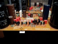
The capacitor 2.2 uF (63V) what is a good capacitor for this position?
And is this capacitor important for the sound of the amplifier?
Regards,
Rudy
And is this capacitor important for the sound of the amplifier?
Regards,
Rudy
Attachments
Last edited:
Byron, nice work! I can see why it took a little longer. Thx for posting a pic. I was looking at the same chassis and torids. I'm looking forward to your review after it breaks in. I'd love to have a set of these boards...........
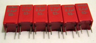
The schematics states a 1uF for that position... I'll stick with the value on the schematics. This is a coupling cap, the small line signal passes entirely through it, indeed making it critical. I decided to go with metallized polyester film as it seems to be unanimous among the DIY community that it's the best type for that position.
My personal choice is a Vishay MKT1813510014.
Martin.
My personal choice is a Vishay MKT1813510014.
Martin.
I really enjoy hearing about what parts are preferred so I can hopefully get the right parts the first time. It's all about good sound. So let us know your likes and dislikes etc..... Finding the parts is another story!
.. I decided to go with metallized polyester film as it seems to be unanimous among the DIY community that it's the best type for that position.
Martin.
Hi Martin,
You must be kidding about "unanimous among the DIY community" 😉
I prefer pond slime on toad skin caps.
Has anything ever been unanimous?
Francois
If you want a suggestion...use the one you have
If you replace all the boutique fashion parts with cheap, old and used electrolitic condenser you will not perceive any difference.
But do the honest test.... install both in the board and a switch to connect one and other, or one or other, or A or B..... previously measure to be sure your capacitors have the same value in microfarads...if electrolitic, then install the positive to the base if you have positive voltage there (milivolts)... then ask someone to switch these capacitors... the guy will give the name A and B...the operator will mark A with a pen..... no one knows what capacitor is A or B.... you do not know and the operator must promisse not to follow connections to know what is A or B (or he will modulate his voice according to his own preference).... then repeat this test.
I will give you a nice Chocolate Cake...inside cream of eggs in one layer and cream of coconut in the other layer... covered with Chantilly cream and a big strawberry at the top.... also i gonna pay the Coke and you will not have to clean the dishes IF YOU PERCEIVE A DIFFERENCE.
You gonna be surprised... we have beliefs.... faith.... we think the expensive is better...we think the big one is better...we think the red or gold ones are better... we think about the shape, the material.... we never think about sound..... faith is this way.... to believe in something that we have no prove (proof?)..... be happy folks...and enjoy your amplifier...it will play nice and this does not depends your part's choice.... was the circuit selected..the current selected, the bias selected, the surrounding auxiliary sub circuits selection, the VAS selection..... parts, if not entirelly wrong in value will not change the amplifier quality.
But if you really believe the golden one is better....well.... no hopes for you...your are fanatic and this is a disease that has no cure.... be happy.
regards,
Carlos
Hi Martin,
You must be kidding about "unanimous among the DIY community" 😉
I prefer pond slime on toad skin caps.
Has anything ever been unanimous?
Francois
Hi Francois,
You're right, I should've said "based on my own personal research on this forum while seeking for the answer of the exact question that's been asked, it seems that a certain majority, a certain non-minority (or is it a non certain minority) prefers this kind instead of that kind , blahblahblahblah..... blah". I had to order that component anyway because I didn't have it in my "senior parts" box, so one type or another my plan was not to compare this component anyway. I search, found my own suitable answer, ordered, soldered, powered, enjoyed. 😉
That's the long answer. 🙄
Where are you at with your Hx project? Can you share your pictures?
Where are you at with your Hx project? Can you share your pictures?
Thank for allowing me a bit of humor on the caps. You and Carlos are right of course - design/topology is much much more important than boutique parts.
Alas, I have no progress on my DX Blame Mk III-HX. I'm currently finishing my new Elsinore Mk V speakers (hopefully this weekend).
http://www.diyaudio.com/forums/multi-way/97043-elsinore-project-thread.html
After that the HX will follow.
Regards,
Francois
Last edited:
Thank for allowing me a bit of humor on the caps. You and Carlos are right of course - design/topology is much much more important than boutique parts.
Alas, I have no progress on my DX Blame Mk III-HX. I'm currently finishing my new Elsinore Mk V speakers (hopefully this weekend).
http://www.diyaudio.com/forums/multi-way/97043-elsinore-project-thread.html
After that the HX will follow.
Regards,
Francois
Wow, it seems to be quite an ambitious project. Woodworking is a lot more work that many would suspect. When you start working on the Hx, I guess you're gonna have a lot of enjoyment as well. It sounds so sweet and powerful.

Good nite
Martin.
You wouldn't believe what was wrong with my power supply!
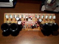
The threaded mounting stud on the bottom of each capacitor is connected to the negative lead. I'm unable to figure out what kind of mental invalid would not only design such a stupid feature, but then not put a word in the description or data sheet telling us that the mounting stud is actually a second negative lead. How many hours of frustration did I waste trying to troubleshoot my PS because some engineer at Kemet didn't have the common sense to put something so important in the data sheet? Or maybe it's my fault. Maybe there is a secret code among electrical engineers which says that mounting studs on all electrolytic capacitors are actually secret leads? And it's so obvious to all EE's that it doesn't need to be mentioned anywhere in the capacitor's description? How could I possibly have guessed this? And when I realized it, I assumed the cap was damaged or defective.
And now how am I going to mount the caps to the chassis? I'll have to get giant rubber grommets, and I'll still have 4 highly charged bolts sticking through the chassis to insulate. What could possibly be the the purpose of such a design? How did the engineers think we were going to mount these? Why the hell would anyone want the negative lead grounded to the chassis, or whatever is holding the capacitor? And if someone did want that design feature, aren't they capable of just running that wire themselves?
It's just a profoundly stupid design feature which serves no purpose, and makes them very difficult to use. The only thing dumber than this design is not mentioning this design flaw in the datasheet.
Well, I'm going to bed now and maybe tomorrow I'll think of some way to salvage these rather expensive capacitors.
Byron! What a find! I've never used that style cap, but I'll keep it in mind what you found. Situations like this is why so many projects get put on the shelf for yrs. You obivously went thru a difficult time. Hopefully it will be smooth sailing now..... Thx for sharing
- Status
- Not open for further replies.
- Home
- Amplifiers
- Solid State
- Dx Blame MKIII-Hx - Builder's thread