you don't need computer software to identify which capacitors have a high or low voltage imposed on them.
Just look at the schematic.
Just look at the schematic.
Very good Meanman.... i am sure you are working on it
We will be waiting your progress...and also counting people interested in a future second round to the group buy.
regards,
Carlos
We will be waiting your progress...and also counting people interested in a future second round to the group buy.
regards,
Carlos
You'll definitely right Andrew, but I had this question several times posted here on the forum but did not get the "correct" answers 😉
I am the person with the least answers, I have a little electro knowledge and therefore my questions might also be useful for others.
Regards,
Rudy
I am the person with the least answers, I have a little electro knowledge and therefore my questions might also be useful for others.
Regards,
Rudy
Last edited:
I cannot respond to your observation, because I know that my response is likely to get me suspended from this Forum.. posted here on the forum but did not get the "correct" answers......
Rudi,very helpfull the pic you've posted.But I also think Alex did a great job and did think about the voltage of the caps
Pity to hear Andrew also because you take a lot of time puts out to help other people.
Regards,
Rudy
Regards,
Rudy
Rudi,very helpfull the pic you've posted.But I also think Alex did a great job and did think about the voltage of the caps
Yes Meanman, you was the person who responded that alex correct intended to smaller voltages to take on this position.
You wake me up thanks for that 😉
Rudi,you could ask Cannonnica how much voltage he has on those caps.My idea is that Alex has a reason for using 63Volt caps there
Regards,
Rudy
Last edited:
It was clearer if the voltage was also printed on the board also at the smaller uF values and not only on the larger uF values.
And better was if we can see the correct values on the schema.
Then everyone can make his own parts list, with equal the correct values.
My two cents
Regards,
Rudy
And better was if we can see the correct values on the schema.
Then everyone can make his own parts list, with equal the correct values.
My two cents
Regards,
Rudy
I hope this gonna help you BMW.... usually builders
knows these voltages because they have already made a couple of amplifiers... reading the supply voltage they conclude..they realise.
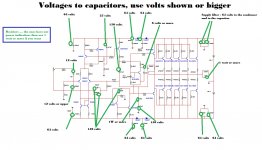
There are some exceptions, the Miller capacitor may face rail to rail voltage...so, 64 volts multiplied by two goes to 128...we use a standard value above this.
Another exception is the NFB (gain) condenser and bypass capacitor associated with it...there we use high voltage too or we protect using two diodes inverted one related the other... and this will allow us to use low voltage condensers and capacitors there.
The zobel filter must be high voltage, there, if you face oscilations, the voltage can reach rail to rail and even more than that as a result of oscilation effects and the presence of inductances associated.
The output resistor, and also the zobel resistor (10 to 22 ohms) use to be 1, 2, 3 or 5 watts
The input capacitor can be the smallest insulation voltage you have..there you gonna have small AC voltage.
The small capacitor in the input, the 220pf can be ceramic, wil face low voltage, it is only an RF drain because of RF that can be picked by wiring.
The condenser into the Bias control circuit, that is also a thermal sensor, is very small.... a couple of volts there..you can use the voltage you want..from 2 volts to 128 volts...this is your decision
These things use to be so obvious that i do not worry about it.... usually people that intend to build has some basic knowledge that is more than enough to realise these things.... and about the rail ones.... of course are superb obvious as they are connected to the supply voltage....so the voltage is there to people to read...the supply rail voltage is the insulating voltage needed.
I am posting an image, special for you, as others have not asked that...i hope this helps BMW.
I am having a nice day in Brasil... a lovely sunny day... i hope this message reach you with good mood too.
regards,
Carlos
knows these voltages because they have already made a couple of amplifiers... reading the supply voltage they conclude..they realise.
There are some exceptions, the Miller capacitor may face rail to rail voltage...so, 64 volts multiplied by two goes to 128...we use a standard value above this.
Another exception is the NFB (gain) condenser and bypass capacitor associated with it...there we use high voltage too or we protect using two diodes inverted one related the other... and this will allow us to use low voltage condensers and capacitors there.
The zobel filter must be high voltage, there, if you face oscilations, the voltage can reach rail to rail and even more than that as a result of oscilation effects and the presence of inductances associated.
The output resistor, and also the zobel resistor (10 to 22 ohms) use to be 1, 2, 3 or 5 watts
The input capacitor can be the smallest insulation voltage you have..there you gonna have small AC voltage.
The small capacitor in the input, the 220pf can be ceramic, wil face low voltage, it is only an RF drain because of RF that can be picked by wiring.
The condenser into the Bias control circuit, that is also a thermal sensor, is very small.... a couple of volts there..you can use the voltage you want..from 2 volts to 128 volts...this is your decision
These things use to be so obvious that i do not worry about it.... usually people that intend to build has some basic knowledge that is more than enough to realise these things.... and about the rail ones.... of course are superb obvious as they are connected to the supply voltage....so the voltage is there to people to read...the supply rail voltage is the insulating voltage needed.
I am posting an image, special for you, as others have not asked that...i hope this helps BMW.
I am having a nice day in Brasil... a lovely sunny day... i hope this message reach you with good mood too.
regards,
Carlos
Attachments

Ear and eye candy 🙂
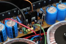
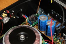
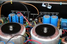
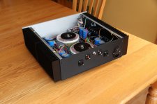
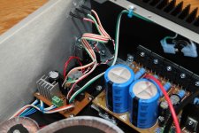
Hello dear friends! My project is now over. It's almost sad to think it's already done. All the wiring and the mechanical assembly seemed endless to me. You got to calculate many hours for doing that step. It's also very hard to wire all of this and keep everything inside good-looking.
As you'll se below, I took many many shots of it before I put the cover on.
I know that for some this can be a never ending project, but to me a project needs to end. And what a wonderful end... Before screwing the cover on, I re-measured the bias on positive and negative sides, DC offset, temperature of CCS and VAS and every measurement was exactly as expected. Enclosed for three hours playing at a moderate level, the CCS and VAS heatsinks reached a peak of 48 degres Celcius at an internal temperature of 31 degres and main heat sinks at 33 degres. I can consider it's perfectly stable. Remember I DID change the CCS resistor for a 47 ohms. Be cautious; If you leave at 22 ohms nobody posted any real world enclosed measurements.
Just for the record:
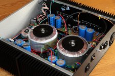
It's built as a dual-mono (except for the speaker protection which is a unique two-channel circuit);
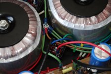
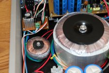
I used two 45V+45V/400VA transfos;
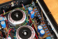
It's built on the red boards of meanman64;
I used all the 5 output pairs for each channel;
I decided to use the lifted audio ground all-the-way;
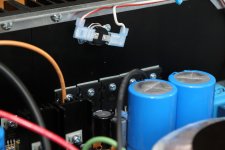
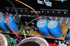
I only use the onboard reservoir capacitors, which are 10000uF each (4 per board);
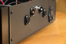
I've put an "undocumented" potentiometer at the line input. I say undocumented because it's on the back panel and is for controlling my friend's musical level when they come visit me, hey my speaker's voice coils are heating faster than the amp!;
I used a connexelectronic soft start and speaker protection circuits;
I've created a standby / power-on / overheat circuit that feeds or cut-off the soft start and speaker prot at once;
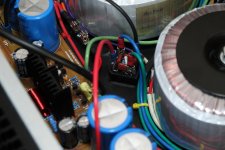
The small transfo you see at the very front is for that specific circuit, it's always powered;
I decided to use RCA input and not XLR; their ground are isolated from the chassis;
I decided to use Neutrik Speakon connectors for speakers;
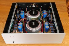
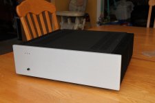
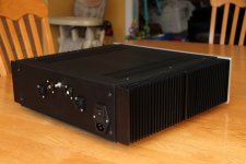
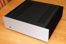
I wanted to have a chassis which is sleak and simple, it's a Pesante Dissipante of 3U height and 400mm deep. Having it in front of me I can tell it's a jewel!! It looks even better in person than on pictures. 🙂
Carlos, Alex, Meanman64 and everybody that shared information, it was a really exciting journey to build this amp and I cannot thank you enough!!
I decided to listen to the live recording "Rush in Rio" tonight, Carlos I know you're not very far from that place, so take it as a tribute. Tomorrow I'll try some Sepultura (metal Bazilian band) at higher levels 😉 (eheh, tastes cannot be disputed) 😀
Merci Carlos d'être ce que tu es, la maison est remplie de musique maintenant!
Here's the pictures!
Martin.
Hello dear friends! My project is now over. It's almost sad to think it's already done. All the wiring and the mechanical assembly seemed endless to me. You got to calculate many hours for doing that step. It's also very hard to wire all of this and keep everything inside good-looking.
As you'll se below, I took many many shots of it before I put the cover on.
I know that for some this can be a never ending project, but to me a project needs to end. And what a wonderful end... Before screwing the cover on, I re-measured the bias on positive and negative sides, DC offset, temperature of CCS and VAS and every measurement was exactly as expected. Enclosed for three hours playing at a moderate level, the CCS and VAS heatsinks reached a peak of 48 degres Celcius at an internal temperature of 31 degres and main heat sinks at 33 degres. I can consider it's perfectly stable. Remember I DID change the CCS resistor for a 47 ohms. Be cautious; If you leave at 22 ohms nobody posted any real world enclosed measurements.
Just for the record:
It's built as a dual-mono (except for the speaker protection which is a unique two-channel circuit);
I used two 45V+45V/400VA transfos;
It's built on the red boards of meanman64;
I used all the 5 output pairs for each channel;
I decided to use the lifted audio ground all-the-way;
I only use the onboard reservoir capacitors, which are 10000uF each (4 per board);
I've put an "undocumented" potentiometer at the line input. I say undocumented because it's on the back panel and is for controlling my friend's musical level when they come visit me, hey my speaker's voice coils are heating faster than the amp!;
I used a connexelectronic soft start and speaker protection circuits;
I've created a standby / power-on / overheat circuit that feeds or cut-off the soft start and speaker prot at once;
The small transfo you see at the very front is for that specific circuit, it's always powered;
I decided to use RCA input and not XLR; their ground are isolated from the chassis;
I decided to use Neutrik Speakon connectors for speakers;
I wanted to have a chassis which is sleak and simple, it's a Pesante Dissipante of 3U height and 400mm deep. Having it in front of me I can tell it's a jewel!! It looks even better in person than on pictures. 🙂
Carlos, Alex, Meanman64 and everybody that shared information, it was a really exciting journey to build this amp and I cannot thank you enough!!
I decided to listen to the live recording "Rush in Rio" tonight, Carlos I know you're not very far from that place, so take it as a tribute. Tomorrow I'll try some Sepultura (metal Bazilian band) at higher levels 😉 (eheh, tastes cannot be disputed) 😀
Merci Carlos d'être ce que tu es, la maison est remplie de musique maintenant!
Here's the pictures!
Martin.
Attachments


Ok max 10 pics. here's more
Attachments

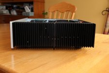
Showoff... I'm still milling around with chassis material... 🙂 Great job and nice looking case, wiring and layout is neat and tidy as it should be, well done Martin ..

A perfect work, missing only the potentiometer volume button. I'm glad I brought my little contribution to the amplifier. Congratulations on your achievement and enjoy it.🙂
Alex.
Alex.
Recycling old amps???
I'm surprised to see no one has used an old blown power amp for the project? It seems everyone has at least 1 blown amp in their basement. Chassis, heat sinks, transformers are waiting to be used. Old PA amps from the past Rock & Roll boom. I think they are built more solid than the current production amps. Anybody feel similiar? If you got an old amp, put it up for sale on DIY.
I'm surprised to see no one has used an old blown power amp for the project? It seems everyone has at least 1 blown amp in their basement. Chassis, heat sinks, transformers are waiting to be used. Old PA amps from the past Rock & Roll boom. I think they are built more solid than the current production amps. Anybody feel similiar? If you got an old amp, put it up for sale on DIY.
I can see you are not a believer in small loop area for flow and return wire pairs.
I think your amp performance can only improve, if you twist the relevant flow and return pairs.
AC mains, AC secondaries. PSU DC, speaker, signal input. All these pairs will each show a small benefit. The total benefit can be the making or breaking of amplifier performance. auxiliary supplies, both ac & dc
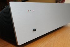
"Buen trabajo Canonnica" Good job Canonnica
Beautiful Canonnica very nice and tight wiring!"me gusta to trabajo" my still a skeleton but is all good I'm happy with what I got so far.
regards
vargasmongo3435
Beautiful Canonnica very nice and tight wiring!"me gusta to trabajo" my still a skeleton but is all good I'm happy with what I got so far.
regards
vargasmongo3435
Last edited:
Keep posting these nice pictures Cannonica
A beautiful amplifier... and a professional photographer.
regards,
Carlos
A beautiful amplifier... and a professional photographer.
regards,
Carlos
- Status
- Not open for further replies.
- Home
- Amplifiers
- Solid State
- Dx Blame MKIII-Hx - Builder's thread