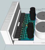
About heatsink size, output power and transformer selection
This was published in the group buy thread, as people is subscribed there too... so, i use to publish something there.
Here is the copy:
The big heatsinks i am suggesting is to face heavy duty work
--------------------------------------------------------------------------------
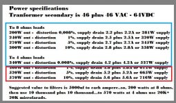
Full power, distorted power of 10 percent.... continuous distorted power...playing already distorted masters, modern electronic music or Heavy metal distorted music.... two channels driven and using two huge transformers of 2 kilowatts each one of them....so.... the available power, when distorting, will be huge, will go to 1 kilowatt each channel (2 ohms)
And believe me or not, there are guys that does not perceive that as bad sound...they understand that sittuation as "loud sound"...some guys feels distortions as "crisp" sound because introduces harmonics and sound starts to have more "body".... seems more solid...i do think it is awfull, but i see that many guys does not mind... the ones loves distorted, already clipped guitar tones (already present in the audio source recording) do not mind...for them this is much more an effect than a defect.
For "normal", standard use... to average listeners.... the ones does not accept distortion, these 15 by 30 centimeters heatsinks (2 pieces of 15 by 15 attached together in the picture), to one channel, will be good enougth to operate at 8 ohms with continuous undistorted tones (250 watts RMS) and will be good also for musical 500 watts... seems the average is 250 watts and you have peaks that will reach 500 watts or more.... listening normal music, not modern electronic music.... a jazz music, a classical music for instance.
My suggestion to use 7 times this heatsink shown is to heavy duty.... two channels as i said...pumping horrible continuous distorted sound at 10 percent THD levels...two channels playing.... so... power transistor will survive to such kind of torture.
You do not need to do this way if your transformer is smaller....your power to each channel will be, let's say limited, by 50 percent (aprox.) of your transformer power....so, if you select two 600 to 700 watts transformers, then your avaiable power may be around 350 - 450 watts RMS to each channel and this heatsinks shown in the 3D picture will be good for 8 and for 4 ohms...and i do think this is the most rational use.... instead to push the unit to produce 2 kilowatts in stereo with 10 percent distortion (chip amplifiers uses 10 percent specification because people really goes to this level... average people... no audiophile people...less demanding people)
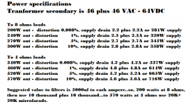
Please, watch the power specifications to 8 ohms and 4 ohms.... this gonna be the most used condition i suppose... watch the demand of transformer power, the continuous power and distortion levels.... your transformer power will be what will decide the power you will be able to put out from your amplifier...so.... take care about this decision and select heatsinks, rectifiers, electrolitic condenser bank.... all this in order to face your custom use...not to waste money buying giant transformers that will never be needed to your particular application.
So, select your power transformer in order to match your power needs...if you need 150 undistorted watts to each channel, if you do not tollerate distortion, then you will be running at this maximum power level...maybe to match your expensive speaker power ration, then select two 300 watts transformers or a single 600 watts transformer.... this will limit your power if you do not increase further entering distortion.... will protect and match your speaker and will save your money in heatsinks, rectifiers, electrolitic condensers, size of your case and transformer...will avoid to waste money and will save your speaker coil to be melted by a crazy kilowatt. sustained power.
Observe that your selection will save money a lot.... to 200 watts you will need 10 thousand plus 10 thousand microfarads to each channel.... two 5A bridge rectifiers will be good...heatsinks will not be that huge...transformer will not be that big too.
Adjust your power amplifier iddle current in order to read 1 milivolt Dc developed across your power emitter resistors, the ones are installed at the power transistor emitters, you have one resistor in each emitter, they may read not that different voltage if they are matched...this will guarantee cool operation.
regards,
Carlos
This was published in the group buy thread, as people is subscribed there too... so, i use to publish something there.
Here is the copy:
The big heatsinks i am suggesting is to face heavy duty work
--------------------------------------------------------------------------------
Full power, distorted power of 10 percent.... continuous distorted power...playing already distorted masters, modern electronic music or Heavy metal distorted music.... two channels driven and using two huge transformers of 2 kilowatts each one of them....so.... the available power, when distorting, will be huge, will go to 1 kilowatt each channel (2 ohms)
And believe me or not, there are guys that does not perceive that as bad sound...they understand that sittuation as "loud sound"...some guys feels distortions as "crisp" sound because introduces harmonics and sound starts to have more "body".... seems more solid...i do think it is awfull, but i see that many guys does not mind... the ones loves distorted, already clipped guitar tones (already present in the audio source recording) do not mind...for them this is much more an effect than a defect.
For "normal", standard use... to average listeners.... the ones does not accept distortion, these 15 by 30 centimeters heatsinks (2 pieces of 15 by 15 attached together in the picture), to one channel, will be good enougth to operate at 8 ohms with continuous undistorted tones (250 watts RMS) and will be good also for musical 500 watts... seems the average is 250 watts and you have peaks that will reach 500 watts or more.... listening normal music, not modern electronic music.... a jazz music, a classical music for instance.
My suggestion to use 7 times this heatsink shown is to heavy duty.... two channels as i said...pumping horrible continuous distorted sound at 10 percent THD levels...two channels playing.... so... power transistor will survive to such kind of torture.
You do not need to do this way if your transformer is smaller....your power to each channel will be, let's say limited, by 50 percent (aprox.) of your transformer power....so, if you select two 600 to 700 watts transformers, then your avaiable power may be around 350 - 450 watts RMS to each channel and this heatsinks shown in the 3D picture will be good for 8 and for 4 ohms...and i do think this is the most rational use.... instead to push the unit to produce 2 kilowatts in stereo with 10 percent distortion (chip amplifiers uses 10 percent specification because people really goes to this level... average people... no audiophile people...less demanding people)
Please, watch the power specifications to 8 ohms and 4 ohms.... this gonna be the most used condition i suppose... watch the demand of transformer power, the continuous power and distortion levels.... your transformer power will be what will decide the power you will be able to put out from your amplifier...so.... take care about this decision and select heatsinks, rectifiers, electrolitic condenser bank.... all this in order to face your custom use...not to waste money buying giant transformers that will never be needed to your particular application.
So, select your power transformer in order to match your power needs...if you need 150 undistorted watts to each channel, if you do not tollerate distortion, then you will be running at this maximum power level...maybe to match your expensive speaker power ration, then select two 300 watts transformers or a single 600 watts transformer.... this will limit your power if you do not increase further entering distortion.... will protect and match your speaker and will save your money in heatsinks, rectifiers, electrolitic condensers, size of your case and transformer...will avoid to waste money and will save your speaker coil to be melted by a crazy kilowatt. sustained power.
Observe that your selection will save money a lot.... to 200 watts you will need 10 thousand plus 10 thousand microfarads to each channel.... two 5A bridge rectifiers will be good...heatsinks will not be that huge...transformer will not be that big too.
Adjust your power amplifier iddle current in order to read 1 milivolt Dc developed across your power emitter resistors, the ones are installed at the power transistor emitters, you have one resistor in each emitter, they may read not that different voltage if they are matched...this will guarantee cool operation.
regards,
Carlos
Attachments
Last edited:
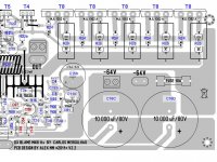
Ideas to implement recent changes
I have some ideas about the correction Carlos posted in post#10 and also post#127 In the group buy forum.
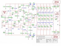
The boards were already ordered, and were being made when Carlos posted the change. I’ve been trying to figure out how the change can be made with the existing boards (currently on a FedEx truck). First, I’ll replace the previous numbered schematic and board layout with these new ones. If you look at the new schematic, you see that the changes 1) add a 10ohm resistor (named R31 and written in red) between signal ground and R01, R17, C04, C06 and C07, and 2) redirect R17 from ground to R01, C04, C06 and C07.
Now, if you look at the right side of the board layout, you see that C04, C06 and C07 (in red) are all connected to the same track, which winds its way around to signal ground on the left/middle/bottom of the board. It would seem that this track must be cut somewhere left of C07, then the cut bridged with our new resistor (R31). Because R30 is optional, and will probably not be used by most builders, its upper hole seems a convenient place to put one end of the new resistor. I guess we’ll just have to scrape away soldermask to mount the other end of R31.
It would seem that R17 (also in red) can be flipped around so the end which used to go to signal ground now attaches somewhere to that track which connects C04, C06 and C07.
That leaves R01. The only effect of the change that I can see is to put R31 between it and ground. Because R01 is already 47K, it doesn’t seem that an additional 10ohms will do much. I assume, then, that we can leave R01 alone. This would mean the schematic would actually have R31 in between R01 and C04, with R01 going straight to signal ground.
I’d appreciate people’s thoughts, especially Carlos’ input.
-Byron
I have some ideas about the correction Carlos posted in post#10 and also post#127 In the group buy forum.
The boards were already ordered, and were being made when Carlos posted the change. I’ve been trying to figure out how the change can be made with the existing boards (currently on a FedEx truck). First, I’ll replace the previous numbered schematic and board layout with these new ones. If you look at the new schematic, you see that the changes 1) add a 10ohm resistor (named R31 and written in red) between signal ground and R01, R17, C04, C06 and C07, and 2) redirect R17 from ground to R01, C04, C06 and C07.
Now, if you look at the right side of the board layout, you see that C04, C06 and C07 (in red) are all connected to the same track, which winds its way around to signal ground on the left/middle/bottom of the board. It would seem that this track must be cut somewhere left of C07, then the cut bridged with our new resistor (R31). Because R30 is optional, and will probably not be used by most builders, its upper hole seems a convenient place to put one end of the new resistor. I guess we’ll just have to scrape away soldermask to mount the other end of R31.
It would seem that R17 (also in red) can be flipped around so the end which used to go to signal ground now attaches somewhere to that track which connects C04, C06 and C07.
That leaves R01. The only effect of the change that I can see is to put R31 between it and ground. Because R01 is already 47K, it doesn’t seem that an additional 10ohms will do much. I assume, then, that we can leave R01 alone. This would mean the schematic would actually have R31 in between R01 and C04, with R01 going straight to signal ground.
I’d appreciate people’s thoughts, especially Carlos’ input.
-Byron
Attachments

Oh!... all these numbers drives me confused dear Byron
The 10 ohms was already there.... in the original layout from Alex mm.... i do think there is anything to fix...the input ground in alex schematic is already floating (lifted ground)...he made that way...not problems to keep the way he made.
I do not know if i am too much stupid but i could not understand.... modifications?... why?.... is your board different while compared to the schematic?.
Well...today i am not feeling very well....tomorrow i will try to understand your post.
You know... the last schematic has the ground lifted the way Alex mm have made.... so...anything to fix..... ME....uncle charlie is the one HAD to do something...and what i did?...i have included the 10 ohms resistor in the schematic on order not to be different if people compare the schematic and board...board was checked...no error...the only one was that 330/390 ohms resistor...anything more to be fixed.
You know dear Byron.... i have made a new schematic to include the resistor...it was not placed in the previous schematics published...then Alex mm included...he thought i forgot (was not really this way..was my decision to remove) that lifting 10 ohms resistor, the lifted ground..the low noise ground to the input circuit....i have made the schematic to match board...in order NOT TO BE NEEDED to change anything in the board or to provide instructions to forum guys...i am confused.... and result the opposite?..... i made the schematic in order to match the board... to avoid to instruct guys about new parts...the 10 ohms was already there...was only a bureaucratic decision to fix the schematic to avoid confusion.... there's anything that needs to be changed... the board, unless the one i revised, is the same Alex mm board design.
All these numbers confuses me....my brain does not accept these numbers and it blocks the entrance in my neuroniums....i do not use these numbers.....i use values in the board....so, to follow these numbers to understand what you mean is the ultimate torture to uncle charlie...i do think these numbers are terrible...the identification numbers is something i have avoided ...was a big figth to be rid of them man... and now you bring them back to life.🙁😕😱
Please, watch the image Byron....resistor is in place.... even the board that had mistake from the Advance Circuits had the resistor in the correct position..what is going on?
regards,
Carlos
Attachments

Last edited:
I finally could understand.... was not that easy
as i am not feeling very well today.... vision is confused (i do not drink or use drugs...not even a beer..i do not like alcohol)..... i am strange today.
I see the resistor is not provided into the board...the 10 ohms lifting resistor is not there....maybe is that you intend to say... no problems...it is all right, amplifier works fine without it and also works fine with it.
You have concerns how to wire the 1K to the lifted ground too....no problems, it can be out from the lifted ground.... can keep it the way it is...it is direct to the ground and will work fine this way too.
I hope this is what you meant.....so... it is all rigth.
This 10 ohms resistors is such a long story that i feel lazy to comment...i suppose i have explained that in audio to you, or videos published or posted in the forum...for sure i have explained.... let it be....too much long to repeat.
These ID numbers produces a short circuit inside my mind...i hate that stuff.
regards,
Carlos
Last edited:
...... pcb in the mirror ?
Sorry but I dont understand what hepend with my designed PCB for MK III HX ?!😕 All components will be soldered on bottom side ????? and silk screen on pads???? I'm totally disappointed he could get out PCB's of the factory 😱 To many comments regarding 10 ohm resistor , what big deal , make an link with wire (shortcut) .
Alex.
Attachments
Was a mistake from Advance Circuits...but they have accepted
to manufacture boards once again...these ones (picture) gone to the trash box.
People will have new boards with all that stuff fixed....boards are on the way to Byron home.
regards,
Carlos
to manufacture boards once again...these ones (picture) gone to the trash box.
People will have new boards with all that stuff fixed....boards are on the way to Byron home.
regards,
Carlos
Last edited:
About lift ground.... comments here
About lifted ground to MKIII-Hx input. - YouTube
regards,
Carlos
About lifted ground to MKIII-Hx input. - YouTube
regards,
Carlos
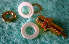
The input connector, the RCA type connector to MKIII-Hx input
Image attached and a video link down here:
RCA connector input for MKIII Hx - YouTube
regards,
Carlos
Image attached and a video link down here:
RCA connector input for MKIII Hx - YouTube
regards,
Carlos
Attachments
Now I understand
I didn't realize that the 10ohm resistor you added to the schematic is the same optional 10ohm resistor Alex added. I though is was a new component which was not in the board. So we can all just forget everything I wrote about cutting tracks and scraping off soldermask.
I didn't realize that the 10ohm resistor you added to the schematic is the same optional 10ohm resistor Alex added. I though is was a new component which was not in the board. So we can all just forget everything I wrote about cutting tracks and scraping off soldermask.
It is all right Byron...both ways are fine
Last videos made about Dx amplifiers...the input connector, the lifted ground is here:
RCA input connector for MKIII Hx - YouTube
And here you have the Star ground, and noise pickup that sometimes happens when using some potentiometer brands:
Star ground and potentiometer noise pickup in Dx amplifiers - YouTube
regards,
Carlos
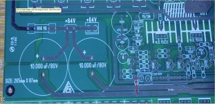
Here you have the star ground... the traditional way
You see the white thick line is the transformer secondary center tap...it is not made as the star ground central point.... was used a more centralized idea..and works perfectly both ways.
regards,
Carlos
You see the white thick line is the transformer secondary center tap...it is not made as the star ground central point.... was used a more centralized idea..and works perfectly both ways.
regards,
Carlos
Attachments

How to connect audio cables to you Dx amplifier volume control
Video shows:
Volume control to Dx amplifiers - YouTube
regards,
Carlos
Video shows:
Volume control to Dx amplifiers - YouTube
regards,
Carlos
How to wire your power supply for MKIII-Hx
Here you have instructions:
How to wire a supply for MKIII-Hx - YouTube
regards,
Carlos
Here you have instructions:
How to wire a supply for MKIII-Hx - YouTube
regards,
Carlos
Now a days, videos are the main support you have...of course
the thread has informs too and i am here to answer your questions...but in this video, 25 minutes position, you have how to adjust your MKIII-Hx amplifier.
Monologue detailing the MKIII-Hx power audio amp. - YouTube
In the future i put instructions at Greg pages, but not immediately as i have to assemble and produce pictures.
regards,
Carlos
Heatsinks
Can I use this heatsink or is this one too small ?
250x40x150mm, 0,44 K/W
They also have another type (300x40x150mm, 0,35 K/W)that is somewhat larger but those other (250x40x150mm, 0,44 K/W) is better in my cabinet.
Sorry that I ask, because I don't know how this is to calculate.
Regards,
Rudy
Can I use this heatsink or is this one too small ?
250x40x150mm, 0,44 K/W
They also have another type (300x40x150mm, 0,35 K/W)that is somewhat larger but those other (250x40x150mm, 0,44 K/W) is better in my cabinet.
Sorry that I ask, because I don't know how this is to calculate.
Regards,
Rudy
Attachments
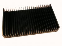
I will study your heatsink....but for a while, about transistors
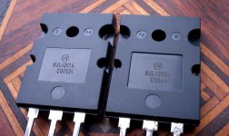
transistors suggested to use together Dx amplifiers are these models attached as picture..these ones where tested...they are reliable.
This was posted in many places, also video was made suggesting I know that in our board layout we have other transistors suggested…but the ones I do point as “tested units” are the ones you see in the attached picture.
The problem is that i have not these more modern models in my simulator, reason why the schematic produced by the simulator are showing different transistors compared to the ones i suggest..the ones i have used to test my amplifiers, the ones i trust the most, because stronger than others.
These power transistors are alike cousin, they belong to a family... their characteristics and specifications are not all that different...they compete offering almost the same performance.....but these ones are one of the best, top performers, to this case style..... for a while, because soon will be beat too.
The suggested transistors, are the ones accept to work with a little bit more current with our voltage supply of 63 volts, they are good for amplifiers from 50 to 70 volts as they deliver high current under this voltage....more than several others... reason why they where selected in order for you to overdrive your amplifier while using 2 ohms loads.... as you will distort, will reach 1 kilowatt or more of power without destroy the output transistors....this is good...this is reliable...even if someone decide to push the amplifier hard..even if speaker coil starts to short nearby windings and reduce the impedance...even this way the amplifier may survive... reliability was the intention when i have selected these transistors....but of course, other models may fit too.
These ones you bought are good too...but not that good to face 2 ohms... i do think they will work with 4 ohms in a very comfortable way...so.... these transistors pointed are not wrong...they are just less powerful.
If you will not push your amplifier hard..if your speakers are not that powerful..if you do not like distorted music, if your application is hobby, home music...then these transistors pointed in the schematic will be good.
But if you will distort, push the amplifier hard, if you will install series and parallel connections of multiple speakers, PA applications, parties, clubs, meetings, big halls needing powerfull sound, cinema, outdoor uses, heavy duty applications, rock bands, theater and so on..then it is better to use the heavy duty transistors, giant heatsinks, fan blowers and boards with speaker protection too.
No...these does not sound better.... this usually does not happens or we usually do not listen advantage from model to model..only instruments use to perceive..some advantages in high frequency can happens but you will notice only if you compare one channel with a transistor model with another channel using other transistor model..differences are but are not that big....this selection is for reliability..not for sonics.
regards,
Carlos
Attachments
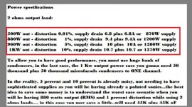
Your heatsink is good for 200 watts continuous
or 400 watts of music power.... say.... a 400 watts power amplifier playing at normal undistorted levels may work fine with your heatsink.
So, two units alike that will be good to the blue are...so...if you will use 4 ohms you cannot go deep into distortions or you gonna have overheat and output transistors may be destroyed.
The red area is the one where you will not be able to be operating...so...to use these heatsinks, externally, one each enclosure side, you will have to buy two 550 watts (550VA) transformers, or a single supply having a 1.1 kilowatt transformer.
Condensers will be 25000uf plus 25000uf to each channel or if you use a single supply, then your condensers will be 50 thousand plus 50 thousand microfarads....your fuses will be 5 plus 5A to each power amplifier rails..and the output fuse will be 10 amperes to each channel....your input fuse, to your transformer primary will be 4A at 120 volts and if you use a single supply, then your mains fuse, to the transformer primary winding will be 8A.
Transformer can be the limiting factor..use it as limiting factor because your heatsink is really small.
So, because your heatsinks (2 units)...you amplifier will be a 200 plus 200 watts RMS amplifier at 8 ohms or a 340 plus 340W power amplifier (4 ohms) having low distorted peaks at 400 plus 400W (4 ohms).
This gonna be your specification... a conservative ratio.
regards,
Carlos
Attachments
Last edited:
Hi Carlos,
Thanks for your explanation, let's see if I can find a larger heatsink otherwise I continue simply to this one.
Regards,
Rudy
Thanks for your explanation, let's see if I can find a larger heatsink otherwise I continue simply to this one.
Regards,
Rudy
I am uploading video about it
So, you will be able to figure out when a heatsink is good and for what power it is good.
Link will be posted here.
regards,
Carlos
So, you will be able to figure out when a heatsink is good and for what power it is good.
Link will be posted here.
regards,
Carlos
Heatsink dimensions, how to figure out their capabilities
here:
Heatsink dimensions, how to figure out their capabilities - YouTube
regards,
Carlos
here:
Heatsink dimensions, how to figure out their capabilities - YouTube
regards,
Carlos
- Status
- Not open for further replies.
- Home
- Amplifiers
- Solid State
- Dx Blame MKIII-Hx - Builder's thread