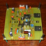
Don't be afraid, Dx amplifiers does not bite us, seems crowdy because
There's a lot of informations in the same image, this is very good, and also produces some fear when we watch.
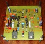
Here a another image, this one Less dense, less overcrowded, less threatening.
Never fear, uncle Charlie is here!
Carlos
There's a lot of informations in the same image, this is very good, and also produces some fear when we watch.
Here a another image, this one Less dense, less overcrowded, less threatening.
Never fear, uncle Charlie is here!
Carlos
Attachments
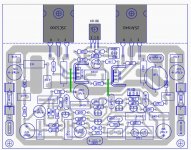
Another error was found,and i have several brazilians observing this, also Taj and me
And we watch without see...this is a terrible human characteristic, we do a lot of mistakes.
This electrolitic condenser have the wrong polarity indicated, the positive goes to the VBE multiplier transistor colector.
regards,
Carlos
And we watch without see...this is a terrible human characteristic, we do a lot of mistakes.
This electrolitic condenser have the wrong polarity indicated, the positive goes to the VBE multiplier transistor colector.
regards,
Carlos
Attachments
Thank you dear Taj
It was a non polarized capacitor, then i have changed to electrolitic, this creates the whole confusion.
regards,
Carlos
It was a non polarized capacitor, then i have changed to electrolitic, this creates the whole confusion.
regards,
Carlos
Search and fix errors, failures, mistakes, shorts, damaged parts in a diy audio power
amplifier:
First job is to check the board, because when we prepare boards, or when we etch at home, we may have failures as copper lines missed, and during soldering you may have shorts.
So, prepare a schematic copy, a printed schematic and a colour pencil or pen and go watching the board througth strong light, put a light bulb bellow the board and go inspecting traces, proceed painting each one of them in your schematic, till you have painted all schematic, trace these lines covering or in parallel with the schematic lines, do it very near the black horizontal and vertical lines that constitutes the circuit connection lines... doing this you will find missed lines, shorted lines and interrupted (broken) lines.
Solder once again each solder point, melt the solder and add a little bit of new solder, if you face bubbles in the solder point, there's a bad solder, a problem you may have fixed soldering these points once again.
Then, having all connections removed, as input cable, output cable, positive rail wire, negative rail wire, ground (VBE multiplier too) them measure resistance to search for semiconductors, or transistors shorted, lines shorted that you could not discover with visual inspection...measure resistance, high scale, 2 Megaohms or 20 Megaohms, you may be patient to wait the meter reading, it will charge electrolitic condensers and will having strange numbers floating, depending the polarity, resistance may reduce to zero and them increase again till will be stable reading several kiloohms, more than 30K, usually you have more than 500K when everything is all rigth.
Do that from positive to ground, and them invert your multimeter probe tips and measure once again.... register the numbers in a piece of paper, make your notes about the resistances you have found.
Do that now from negative to ground and them invert your multimeter probe tips once again, take notes from the values you have,
Now check from positive to negative and invert your multimeter probe points.
All reading should be high resistances... ohms reading, less than 2K, means shorts.
Having shorts...good!, now clean you board with a brush, cut your brush hairs to make the brush tight, reduce the brush hair length to make it strong to remove solder flux, use Alcohol, 92 degrees (to medicine use) or use Kerozene, the aviation fuel, remove all flux, clean your board, let it dry or force it dry using hair dryer or sun light..measure once again..... short continues?
Then check each transistor, observe first if colector is connected to the colector resistance, check the base if is is connected to the base resistance or with other component, and check emitter, do that using light bellow the board, watch the component side, and copper tracks will appear because board will be transparent to the light... copper tracks will be dark because ligth does not cross metal tracks.. them remove the one you have inspected, write with permanent pen the leads position to put it back once again, write (B) for base, (C) for colector and (E) for emitter...
It is needed to remove transistors, to pick them out from the board, sometimes you find transistor shorted, resistance will be zero, but board use to fool us, so, better will be to remove one by one, you will see that this will save time in the place to spend time as you may think, to be thinking and analising takes too much time, better is to remove them all and meaure them outside, the board has resistances, diodes, and other components that may fool you, you may be reading the next transistor and the one under measurement may be open, not conducting. you may think it is fine, but you were measuring other connected to the first one..so, remove them from the board, always do that job, seems stupid, you gonna see that it is not, save time!
...then go removing transistors, one by one, do not remove all them, go one by one, and you will find the shorted one... them replace that one and continue, you may have other, or others....if you remove all, then you will searching for troubles, as you may return them in a wrong way, you may even install a npn in a pnp place.
Doing that you must check if you are using the correct transistor, and you may check in the internet to be sure about the transistor lead position, so, datasheet is there, in the internet, published to help you...check the base lead, the colector lead and emitter lead, you should download data sheet and watch this carefull, also check three times if you are using a NPN in a place you need a NPN and if you are using a PNP in a place you need PNP....so , transistor will be checked...also you will find fake ones, there are NPN fakes that measure alike PNP.... yes...happened this week with a friend.
Check all transistors.... short remains?... then check if output transistor case is insulated related the heatsink, the output transistor's colectors cannot show resistance to the heatsink, heatsink is usually grounded, a wire must go from a heatsink screw (soldered) to the transformer secondary coil center tap pin, the traditional grounding system.... your colector can be shorted with the heatsink, you have already checked all transistors disconnected (out from the board) so, you know they are fine.... so, colector shorted against the heatsink means positive rail or negative rail shorted to ground.
Now electrolitic condensers, remove them and check them, also check if you have installed them in the correct polarity and check the value you have used... if you had electrolitic condensers installed in the opposite polarity, then trow them in the garbage can, they may create future troubles, better to discard these ones submited to inverted polarity.
Now check resistances, each one of them, go painting into the schematic each one you lift one side to measure..let the one side soldered and measure, this way you will not have the circuit resistances fooling you... take this chance to check values with your multimeter, check value comparing with the schematic value... do not believe yourself, you’re human, you make several failures each day, the first and main mistake is to think you have not made any mistake.
Doing that, is almost impossible to remain a failure...but it is hard work, do not engage your brain, it is hard, mechanicall, automatic work, to desolder, to remove parts, to take notes, to measure, and to return to the board, one by one... use your Hypothalamus, your ancient brain only...work mechanically with low intelligence level needed, give a break and a good rest to your brain and engage the monkey automatic features we all have.
This is what i can do to help you..do not waste your time trying to analise why negative rail is having so big power consumption, go measuring and you will find your mistake..measure everything, all capacitors, all condensers, all resistances, all diodes and all transistors..check trimpot, vbe multipler, supply voltages, supply rectifiers and so on..if anything wrong was found, give yourself a break, try in another day, you may be tired, more than one hours doing that use to reduce our attention..try once again latter, or another day.
regards,
Carlos
How to adjust you Dx Blame ES top performance audio amplifier
1) Remove the rail fuses
2) Install DC voltimeter in the fuse socket with fuse previously removed
3) switch on the amplifier power supply
4) adjust bias trimpot to read from 3.3 to 6 volts over the 100 ohms series resistor
5) Check both rails
6) Move DC voltimeter to the output line
7) Off set reading should be from 3 to 25 milivolts, usually it is 12mV
8) Reduce it if you want, place 820, 1K, 1K2 or 1K5 resistance in parallel with
R8
9) Switch your multimeter selector to ready AC volts and read the output line,
no AC voltage should be there.
0) Check once again your stand by current, if fine, them install fuses and
enjoy your amplifier.
If you experience overflow, or variations in the offset readings, them short the input to ground, after that, do not forget to remove the short you have made.
My home amplifiers, the prototypes, one used 1K resistance to reduce off set to 500 microvolts, the other has used 1K2, so, as you see, this is variable, depends on the differential transistor matching and some amplifier components.
The stand by bias trimpot is also something that changes depending the circuit, a good starting adjustment is 250 ohms, as one of my amplifiers asked for 160 ohms and the other was 330 ohms.
Adjusting your bias at 38 miliamperes, your output transistor will be draining 27 mA each one of them, the negative rail current will be 42 mA, the 100 ohms protective resistance reading will be 3.8V up rail and 4.2V the lower rail,
The amplifier itself, has very low power consumption, the output is adjusted to dissipate, during stand by. 1 watt to each power transistor.
Driver transistors needs heatsinks, and it is a very good idea to install as small piece of aluminium, squared, 2 centimeters side, at the second voltage amplifier,the BD139.
its too late to start building ... tomorrow morning and before coffee I will do this job..
with some Brazilian coffee it will be a great ..
thanks Carlos
with some Brazilian coffee it will be a great ..
thanks Carlos
Great funky, Brazilian Coffee came from Arabian countries centuries ago
It is not natural from South America, was planted here.
We love it very strong, very dark with a lot of suggar, some poeple mix with milk (cream) but the majority prefer it hot with suggar only.
regards,
Carlos
It is not natural from South America, was planted here.
We love it very strong, very dark with a lot of suggar, some poeple mix with milk (cream) but the majority prefer it hot with suggar only.
regards,
Carlos
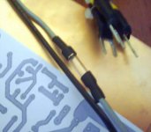
Hello Carlos,
this one:
has been my Christmas-gift this year.
Better than all the Dremel stuff!
Volker and I will start with the DX BlameES this weekend!
Enjoy this day - Rudi
P.S. It is very cold in Germany currently:
this one:
An externally hosted image should be here but it was not working when we last tested it.
has been my Christmas-gift this year.
Better than all the Dremel stuff!
Volker and I will start with the DX BlameES this weekend!
Enjoy this day - Rudi
P.S. It is very cold in Germany currently:
An externally hosted image should be here but it was not working when we last tested it.
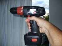
Nice picture, snow here only inside my refrigerator freezer.
I have something alike, have a clutch, have several tools for screws, bolts and nuts, you can control the speed and can work reverse too.
Nice machines, very helpfull for our electronic job, works in slow speed, good to use with metals.
Send to Volker my best regards!
Carlos
I have something alike, have a clutch, have several tools for screws, bolts and nuts, you can control the speed and can work reverse too.
Nice machines, very helpfull for our electronic job, works in slow speed, good to use with metals.
Send to Volker my best regards!
Carlos
Attachments
Last edited:
Carlos,
my DX Intl. Corp. AMPs do have a special design, I can tell you:
My BlameES will be extraordinary as well.
Extraordinary look, extraordinary sound.
Rudi_Ratlos
my DX Intl. Corp. AMPs do have a special design, I can tell you:
An externally hosted image should be here but it was not working when we last tested it.
My BlameES will be extraordinary as well.
Extraordinary look, extraordinary sound.
Rudi_Ratlos
Prepare yourself for a big surprise dear Rudi.
Dx Blame ES eated the Dx Amplifier, was a pitty, but this way is life, the king is dead.
- God save the king!
regards,
Carlos
..............................
You have made a beautifull Dx Amplifier Rudi, one of the best ones ever made.
Congratulations!
Dx Blame ES eated the Dx Amplifier, was a pitty, but this way is life, the king is dead.
- God save the king!
regards,
Carlos
..............................
You have made a beautifull Dx Amplifier Rudi, one of the best ones ever made.
Congratulations!
Last edited:
This one, Carlos, 220nF MKT, will be one of the components playing in "MY BlameES".
Bringing Brazilian sound and feel to Germany.
Best regards - Rudi_Ratlos
An externally hosted image should be here but it was not working when we last tested it.
Bringing Brazilian sound and feel to Germany.
Best regards - Rudi_Ratlos
Last edited:
You will be able to use this capacitor as input capacitor
in the future Dx Blame ES II, when only part values will change, but the same board will be used.
Future input impedance will be 68k.... the same amplifier updated and retuned for bass.
To be tested and released march, 28, 2010
regards,
Carlos
in the future Dx Blame ES II, when only part values will change, but the same board will be used.
Future input impedance will be 68k.... the same amplifier updated and retuned for bass.
To be tested and released march, 28, 2010
regards,
Carlos
Last edited:
Tomorrow morning, having daylight, them will receive a triple check
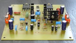
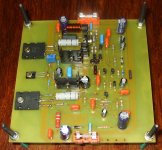
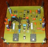
Already found the second differential input transistor inverted..and will find more, as usual.
I will not use these power transistors as output, i have just installed because they are rarities, tomorrow will be replaced by 2SC5200 and complementary, the ones i trust the most.
Also you see 1 ohm power emitter resistance, it is just to show you nice colour at the board face, under the board i have 0.33 ohms resistances.
Well, i will search for errors tomorrow, for sure i will find several mistakes, this is normal and natural, lier is the one say that do not make mistake, this affirmative is already a very big mistake because of arrogance.
regards,
Carlos
Attachments
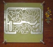
Renato asked me to move some parts and to fix some details
I will do that tomorrow morning.
Renato was the one made the board to me.... he has etched and sent by maild, the board design was Todd Johnson, General Diretor of graphic Arts, PCB Layout, Panels and logos...also President (CEO) from Dx Corporation Canadá.... also Vice President from the entire Corporation.
regards,
Carlos
Attachments
Last edited:
- Status
- Not open for further replies.
- Home
- Amplifiers
- Solid State
- Dx Blame ES .... based into the Blameless, i am trying a new amplifier