Hello Meanman,
I used Greg's PSU (originally designated to the DXAmp) in my design of the BlameES' PSU:
I used MUR860 (MUR1520) as rectifiers and WIMA MKS4 470nF/1000V RM27,5 as bypasses for the big power capacitors.
Works beautifully.
Best regards - Rudi_Ratlos (Vice-Admiral of DXCorp. German division)
I used Greg's PSU (originally designated to the DXAmp) in my design of the BlameES' PSU:
An externally hosted image should be here but it was not working when we last tested it.
I used MUR860 (MUR1520) as rectifiers and WIMA MKS4 470nF/1000V RM27,5 as bypasses for the big power capacitors.
Works beautifully.
Best regards - Rudi_Ratlos (Vice-Admiral of DXCorp. German division)
An externally hosted image should be here but it was not working when we last tested it.
Maybe:
Dutch and German division of DXCorp. Intl. should work together to provide the world with the most beautiful sounding Amp ever.
Rudi_Ratlos - Vice-Admiral of DXCorp. Intl. German Division
Dutch and German division of DXCorp. Intl. should work together to provide the world with the most beautiful sounding Amp ever.
Rudi_Ratlos - Vice-Admiral of DXCorp. Intl. German Division
An externally hosted image should be here but it was not working when we last tested it.
Hi Rudi,
I referred to the 100n and 47n capacitors on the amp board
Also don't forget the Belgian division
I referred to the 100n and 47n capacitors on the amp board
Also don't forget the Belgian division
I won't forget Belgium when I outline the European Support Divison of DXCorp. Intl. !
By the way: I used EPCOS 47nf /100nF / MKT / 100V throughout my BlameES design.
Best regards - Rudi_Ratlos (Vice Admiral of DXCorp. Intl. European Support Division)
By the way: I used EPCOS 47nf /100nF / MKT / 100V throughout my BlameES design.
Best regards - Rudi_Ratlos (Vice Admiral of DXCorp. Intl. European Support Division)
I hope to finish mine before May because we have every year a DIY audio day in Breda Holland.Maybe that's a start of a beautiful audio journey in the Benelux or even whole Europe for the BlameEs.
Nice that Brandenburg Gate and the Bayern cheese.
Thank you dear Rudi... German Division is starting their Blitzkrieg into audio construction....das ist zier gut!
Belgium Division is also installed to promote the amplifier in Amsterdam.....
Yessss...very good that.
regards,
Carlos
Thank you dear Rudi... German Division is starting their Blitzkrieg into audio construction....das ist zier gut!
Belgium Division is also installed to promote the amplifier in Amsterdam.....
Yessss...very good that.
regards,
Carlos
I am building (rigth now) the supply to the active, three way input filter, to be
used in the Dx TriAmp...it will be upgraded using Dx amplifier (boosted) to bass and Dx Blame ES for mids and treble.
hehehehe..... will be the maximum from the maximum, the cream from the cream..the paradise on earth...imagine this way.
Dx Blame alone is already the best amplifier in earth...now imagine having active filter in the input or three amplifiers...audio going to dedicated drivers... separated volume control for bass, mids and treble.
Man, when this starts to play, the "divine" will come to listen and dance with uncle Charlie and will say.
When i have created the thunder, following orders from the master, i would have listened first to this amplifier playing bass..this way thunder sounds could be even better.
Divine is the one responsable by us... audiomaniacs....an anjo!
ahahahahahah!
regards,
Carlos
Doing things, preparing the Dx Triamp...changing input impedance to the Dx Blame ES
But this, new input impedance, only march, 28
regards,
Carlos
But this, new input impedance, only march, 28
regards,
Carlos
An externally hosted image should be here but it was not working when we last tested it.
Nice ones...very nice ones...do not know about the distance from lead to lead
Maybe, (not sure) it can be a little bit big.
I have posted the part list... the BOM..... well, i think i did.
By the way..will post once again.
regards,
Carlos
DX Blame ES parts list (for one channel)
Rev. 1.3 © 2009/2010 Carlos Mergulhão
Transistors:
Device # Value Notes
Q1,Q2,Q3 BC556 Pinout=cbe
Q4,Q5,Q6 BC546 Pinout=cbe
Q7,Q8,Q9 BD139
Q10 BD140
Q11 2SC5200 or FJL4315, or 2SC2922
Q12 2SA1943 or FJL4215, or 2SA1216
Capacitors:
Device # Value Lead Spc Type Notes + Digi-Key part #
C1 10uF 15mm film DK: 495-4092-ND, or use 2 back-to-back electrlytics
C2,C4,C5,C6,C9,C26 100nF 5 or 10mm film DK: polyester 495-2481-3-ND or polypropylene 495-1375-ND
C3 220pF 5mm mica, polystyrene or polyprop. or NP0 or C0G ceramic
C7 220uF/16v 3.5,2.5mm Electrolytic
C8 47uF/25v 2,2.5,3.5mm Electrolytic
C10 47uF/100v 5mm Electrolytic
C11 18pF 5mm mica, polystyrene or polyprop. or NP0 or C0G ceramic
C12 100F/16v 3.5,2.5mm Electrolytic
C13 82pF 5mm mica, polystyrene or polyprop. or NP0 or C0G ceramic
C14,C16,C20,C22 470uF/50v 5mm Electrolytic
C15,C17,C19,C21,C23 47nF 5mm film aka: .047uF, polyprop. or polyester
C18 220nF 5 or 10mm
C24 100pF 5mm mica, polystyrene or polyprop. or NP0 or C0G ceramic
C25 470pF 5mm mica, polystyrene or polyprop. or NP0 or C0G ceramic
Resistors: (all are .25W metal film, except where noted)
Device # Value Power Notes
R1,R16,R17 220R
R2 10K
R3 10R 0.5W
R4,R22 150R
R5,R6 100R
R7 470R
R8,R9 68R
R10 3K
R11,R12 8K2
R13 12K
R14 3K3
R15 2K7
R18,R21 33R
R19 2K
R20 470R
R23,R25 2R2
R26,R27 0R22 5W Mills non-inductive. Digi-Key: MRA05-.22-ND (4x14 mm approx.)
R28 15R 5W (no Mills avail.) Huntington ALSR. Digi-Key: ALSR5F-15-ND (4x14 mm)
R29 10R 5W Mills non-inductive. Digi-Key: MRA05-10-ND (4x14 mm approx.)
R30,31 2x 100R 1W Optional. Mount on underside of board. Used for adjustm., not for audio.
Miscellaneous:
Device # Value Notes
D1,D2 1n4148
D3,D4,D5 1n4001
Bias Trimmer 500R Bourns 3362P single turn or eqv. Digi-Key: 3362P-501LF-ND
Power, output, ground connectors 4x Faston .25" male. Digi-Key: A29938CT-ND
Fuse holders (5x20 mm fuses) 4x Digi-Key: F063-ND or eqv., need 2 per fuse
Heatsinks for drivers 2x Like Digi-Key: HS106-ND but not sure if these fit. Should do.
It is big, you will have to bent your leads to install in 10 milimeters distance
holes.
Well... at the end will fit....Taj let the option (more holes) to bigger condensers too.... things gonna be all rigth.
regards,
Carlos
holes.
Well... at the end will fit....Taj let the option (more holes) to bigger condensers too.... things gonna be all rigth.
regards,
Carlos
ekkart, try resistances in parallel with R8 or R9... try one and try other
Try one OR other..... try resistances of 820 ohms, 1k, 1k2, 1k5, 1k8 in parallel with R9......is this turning things worse?...then try now the same with R8.
Good luck Volker...but....from -25mV to +25mV is considered normal and does not ask for further adjustments
regards,
Carlos
Try one OR other..... try resistances of 820 ohms, 1k, 1k2, 1k5, 1k8 in parallel with R9......is this turning things worse?...then try now the same with R8.
Good luck Volker...but....from -25mV to +25mV is considered normal and does not ask for further adjustments
regards,
Carlos
Last edited:
Couldn't you use a trimpot and use a fix resistor afterwood for R8 and R9?
Again a dom question about the 100n and 47n capacitors is needed to use MKP or will MKT do the job?
Again a dom question about the 100n and 47n capacitors is needed to use MKP or will MKT do the job?
Last edited:
Yes dear Meanman, you can use this method or others
my choice was for the safest one...not the easiest one.
You can use a series of fixed resistance plus a trimpot, both in series, so a 50 ohms trimpot plus a 50 ohms (or 100 ohms) resistance will fit.
But this is dangerous... trimpot cannot stay there...with agging effects it can create troubles... and this means DC in the output when something goes wrong.
Other method is to substitute the degenerative 100 ohms resistances, in the differential emitter by a 220 ohms trimpot.. the center goes to the CCS colector.
A third method is to adjust, fine adjust, the CCS current.... and this is more than dangerous, it is very unsafe.
My choice was the hard work to go selecting resistances, touching R8 and R9, holding resistances with pliers or fingers and checking the off set...having it reduced, then you should solder the resistance in place....over the board, in parallel with R8 or R9 or bellow the board, also in parallel, soldered together R8 or R9... paralleling and keeping the original resistance is the safest way..to open the circuit with solder or defective (old, or junk as i use to do) trimpot, is much more harmfull to DIYers.
You can do the way you want... even to keep the trimpot is possible, but i am afraid this may create future troubles..not a very good idea to have a trimpot in a so sensitive place.... trimpot, better to adjust them and substitute them by a fixed resistance... and the most common is to obtain a resistive reading that does not match comercial, common, standard resistance values...so... you gonna need, after all, to use series and parallel resistances...if you gonna need to use them in parallel...why not to use this way first?
These capacitors, dear Meanman, are used as a low impedance patch for high frequencies to be sent to ground... this way, you can understand this way... as soon as the oscilations (variations of voltage) starts, the low impedance patch, represented by the capacitor in parallel with the inductive electrolitic condenser, will drain this variation to ground.... condensers are inductive, they are constructed in a coiled way...they represent a resistance, a capacitance and also an inductance... coils does not let high frequencies to cross..but the simple capacitor is different and represents a short to these frequencies to travell to the ground.
Dear Meanman, you could save my time and fingers..all these things were explained, in a detailed way, in the Dx amplifier, my amplifier thread...and this was done for beginners or for people, that alike myself, is learning and evoluting... take some time to read, this way you gonna save my finger points typing all that stuff once again.
regards,
Carlos
device choice
Hi Destroyer X
I notice you kept with the BD139/140 -- I realise at the mid driver level there are a huge range of possible choices.
On my own project (and I'd appreciate any comment from anyone on this - http://www.diyaudio.com/forums/solid-state/160755-trying-build-omg.html) I ordered the Sanken 2SA1216 - 2SC2922 - only because I heard they were good and looking at later Mark Levinson and Krell designs as an inspiration.
Out of your list -- do you think the thermal and secondary stability in others are better than my choice? I'm attempting to go with passive (though huge) heatsinks - balancing between collector emitter voltage in the safe operating area and drive current in Class A.
I have to admit not having much experience with this type of device - back in the mid 1990s when this was my job -- the best we had then were MJ15024-15025s
I'd really appreciate anyones thought on this
thanks
Lex
Good morning Meanman,
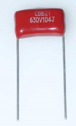
you can use any type of Metallized Polyester Film Capacitors for the 47nF and 100nF caps (f.e. the one you showed).
I will give you the name of some companies who offer a big variety of well-suited capacitors:
Vishay, EPCOS, WIMA, ...
I bought my 47nF/100nF MKTs from EPCOS.
Be aware - as Carlos told you - about the dimension of the capacitors you order.
Some of them should/must have a spacing of 5mm, some of them 10mm.
(As I remember 47nF are 5mm and 100nF are 5 / 10 mm (both options are possible for the 100nF on Todd's board)).
Take a look on Todd's beautiful picture of this board - layout and order the correct dimension.
When it comes to capacitors with values less than 1 nF (4 of them) I took MICA capacitors.
Important - in my ears, in my eyes - is the capacitor on the input (C1).
You can of course use 2 electrolyts to assemble a non-polarized 10µF cap on the input, Todd provides this option on his board, but, if possible,
try and get a MKT (MKP) for C1 (f.e. the one Todd recommended in his BoM)
I use EPCOS MKT 10μF RM15, even tried to mount a "whale cap" (like MUNDORF MCAP, AUDYN, ...) - but these "whales" have been too big.
And be aware of the electrical (voltage) strength of the Zobel cap: C23.
100V is the value I recommend.
I can promise you: the choice of the capacitors listed above will contribute to a divine sound of your BlameES,
crispy heights and very strong, controlled bass - hehehe, Carlos: no shyness at all!.
Best regards - Rudi_Ratlos (Vice-Admiral of DXCorp. Intl. German Division)
An externally hosted image should be here but it was not working when we last tested it.
Last edited:
Good, so the shyness are only inside my head..it is good to know that
Maybe my speakers are fooling me about bass....i am glad to know that Rudi.
...........................................
My dear friend Phaselockyloopy
I do not know those things, as i am focused in my own amplifiers.. try Andrew T, or PMA, or Eva...these ones are some of the main guys to give you some input about those things you said.....PLL is better, your name is a hell to remember and to write.
I do not like theories and theorists, not even to talk about and to discuss...i think they do nothing, just talk...some of them move a little, alike a sick and old disable turtle.... i am a hard worker, the one has a soldering iron always hot..doing and doing things without worries if electrons are blue or orange belted..if they spin clockwise or counterclockwise.... i just make them move, while others goes thinking these details.
regards,
Carlos
Last edited:
Good morning, Lex,
German division of DXCorp. Intl. is using the SANKENs (2SA1216 and 2SC2922)as well.
They sound like the BlameES waited for them to inspire the atmosphere with an orgy of sound.
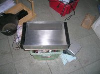
Look how Volker mounted them:
He screwed them directly to his 10mm ALU bottom plate.
And as he told me: they are getting lukewarm even when he plays tracks with lots of bass in them.
He didn't of course feed a 20Hz sinus wave into the input - so the SANKENs (and the BlameES) are not driven to their extent.
So long - no problems with the SANKENs and passive cooling (even though I am still a little bit afraid when it comes to mounting his design into a case).
Best regards - Rudi
German division of DXCorp. Intl. is using the SANKENs (2SA1216 and 2SC2922)as well.
They sound like the BlameES waited for them to inspire the atmosphere with an orgy of sound.
Look how Volker mounted them:
An externally hosted image should be here but it was not working when we last tested it.
He screwed them directly to his 10mm ALU bottom plate.
And as he told me: they are getting lukewarm even when he plays tracks with lots of bass in them.
He didn't of course feed a 20Hz sinus wave into the input - so the SANKENs (and the BlameES) are not driven to their extent.
So long - no problems with the SANKENs and passive cooling (even though I am still a little bit afraid when it comes to mounting his design into a case).
Best regards - Rudi
- Status
- Not open for further replies.
- Home
- Amplifiers
- Solid State
- Dx Blame ES .... based into the Blameless, i am trying a new amplifier