Regulation results of 3 leds vs 2 zeners
LED LTL4231 x 3
I = 2.867mA, V = 5.784V
I = 4.707mA, V = 5.900V
I = 7.832mA, V = 6.068V
2 point slope calc
(6.068-5.784)/(7.832-2.867) = 0.057V/mA Or 57mV/mA
——————————————————————————————————————————————————
2.7V Zener x 2
I = 3.076mA, V = 5.103V
I = 4.848mA, V = 5.420V
I = 7.922mA, V = 5.777V
2 point slope calc
(5.777-5.103V)/(7.922-3.076) = 0.139 V/mA Or 139mV/mA
———————————————————————————————————————————————————
And the WINNER is LTL4231
Ideally I should have produced curves but really we just need to know roughly which is better.
With a Vf of around 1.9V to 2V for this device we only need 3 in series.
Hopefully you can see just by eye balling the data that regulation improves at 5mA and above compared with below 5mA.
I don’t have excel on my new computer yet so I can’t do a simple graph to illustrate this fact but you can see it just by eye balling it.


I am glad you're happy.
I knew you were waiting on these results, so I got my ars3 into gear.
I knew you were waiting on these results, so I got my ars3 into gear.

I'm ordering a set of LTL4231 LEDs, plus a set of E-562 current regulating diodes.
The dumb train is pulling away from the station..
The dumb train is pulling away from the station..
Was the choice of LTL4231 governed by the Papa rule (because they were in the drawer) or were they found to be more consistent such as the Kingbright WP113IDT from the DCB1 Mezmerize?
Since this is Papaland, do you have blue leds to test as well? Is that even necessary, ie is it safe to say that any LED will have flatter tempco than a zener?
Since this is Papaland, do you have blue leds to test as well? Is that even necessary, ie is it safe to say that any LED will have flatter tempco than a zener?
I checked a few alternative LEDs, and saw that the green ones seem to have a greater negative tempco than other colors. I also looked at the infamous "Do not substitute" red LED that is used in the Mtn View IPS of the M2x, which has a fairly low tempco, and good regulation. Probably why it was used there as a voltage reference.
For this application we are looking for a negative tempco for the Vgs reference to help cancel the positive tempco of the output Mosfets in an F6 that has been configured to run at higher bias current. The E-562 diodes also have a small negative tempco, which will help keep the big Mosfets from current drift, though with less effect than the LEDs due to their voltage regulation.
Blue LEDs seem to be exclusively of the "super bright" kind. They probably have a negative tempco as well, but data is more difficult to find.
Last edited:
Erm.. don't max out the bias ?
Could save a lot of time that could otherwise be wasted Listening to muzak ? 😀
Could save a lot of time that could otherwise be wasted Listening to muzak ? 😀
Was the choice of LTL4231 governed by the Papa rule (because they were in the drawer) or were they found to be more consistent such as the Kingbright WP113IDT from the DCB1 Mezmerize?
Since this is Papaland, do you have blue leds to test as well? Is that even necessary, ie is it safe to say that any LED will have flatter tempco than a zener?
Yeah they were in the draw.
I do have blue leds. I can test the ones I have.
Having said that, Walt Jung had done noise measurements on these leds and found them to be very low noise devices.
In general red and green leds tend to be better than blue with respect to noise, although I doubt it matters in F6 given the RC filter that is after the voltage reference in the circuit.
With regards to tempco, the specific problem is that zeners above 5V have a positive temperature coefficient. In F6 we need a voltage reference above 5V so using a 5.6V or 6.2V zener will lead to bias stability problems.
In most cases a zero tempo is what we want, but since we are using the reference to bias a mosfet, having a voltage reference with a small negative tempco will actually be better.
You will see this in the original results. 2 x 2.7V Zeners is much better than either a 5.6v or 6.2V Zener for biasing.
The green led that was tested was a bit better than 2x2.7 zeners.
Last edited:
I'm ordering a set of LTL4231 LEDs, plus a set of E-562 current regulating diodes.
The dumb train is pulling away from the station..
Nice one.
^ Good, that's the version that I ordered.
I also ordered a set of LT4320IN8-1 controllers to see if there's any difference from the plain LT4320IN8.
I also ordered a set of LT4320IN8-1 controllers to see if there's any difference from the plain LT4320IN8.
Last edited:
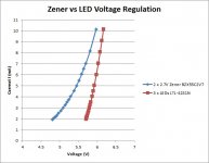
Zener vs LED Voltage Regulation
Decided to do more measurements and produce IV curves of both configurations.
The LED combination is clearly better than the Zener combination.
The Zener combo requires way more current to approach anything that is near the performance of the LED combo.
Decided to do more measurements and produce IV curves of both configurations.
The LED combination is clearly better than the Zener combination.
The Zener combo requires way more current to approach anything that is near the performance of the LED combo.
Attachments
Last edited:
Dumb question: I guess the voltage reference (LEDs or Zeners) needs to be thermally coupled to the power MosFET in some way to achieve good compensation of the FET thermal drift. What's the best way to achieve this?
Half joking half not joking - leave the lid closed.
I don't think the negative tempco is strong enough that it will counteract the positive tempco of the mosfet to compensate for it but also don't think that's the point. The point was that the smaller zener values had better negative tempco than large one so daisy chaining multiple small zeners or leds had better stability. It looks like it also resulted in more consistent bias current as well (smaller delta).
Maybe you're right that thermal coupling would make it better but I just don't see how you would do that. Flat LEDS tape to the heatsink?
Dumb question: I guess the voltage reference (LEDs or Zeners) needs to be thermally coupled to the power MosFET in some way to achieve good compensation of the FET thermal drift. What's the best way to achieve this?
No.
Just the heat radiated off the heat sink does the job. That is how the measurements were carried out.
If you thermally coupled them the effect would be much greater.
You can try it any way you like.
Be aware though, that these results were performed on a heatsink that only gave a 20 C rise above ambient, it will be even better in your actual amp chassis.
Just the heat that is inside the case is enough to have a huge improvement.
I wanted to test this in the dumbest way possible, and it works extremely well. No need for thermal coupling.
Last edited:
- Home
- Amplifiers
- Pass Labs
- Dumb Biasing Mod, applicable to F6 and other Papa Amps. Possibly My Dumbest Idea Yet