Yes indeed, you can't mix and match. The ones I had have an elongated isolation cylinder around the center pin.
I think they are specified for 10kV. They do not fit regular BNC jacks.
Jan
I think they are specified for 10kV. They do not fit regular BNC jacks.
Jan
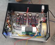
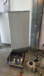
The first amp and modified ESL989 are making sweet noises! Finally a big step forward.
The software needs some finetuning (does anybody know how long the heaters of a 6HS5 need to heat up before anode current starts to flow?).
Next is to get the 2nd channel going, and do some listening tests. And clean up the wiring of course ;-)
Jan
The software needs some finetuning (does anybody know how long the heaters of a 6HS5 need to heat up before anode current starts to flow?).
Next is to get the 2nd channel going, and do some listening tests. And clean up the wiring of course ;-)
Jan
Attachments
Hi Jan,
This looks really interesting. Looking forward to the write up. As I have, for some unknown reason 😉, ended up with a few extra pairs of ESL-63 I might be tempted to try this out.
Mogens
This looks really interesting. Looking forward to the write up. As I have, for some unknown reason 😉, ended up with a few extra pairs of ESL-63 I might be tempted to try this out.
Mogens
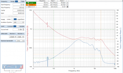
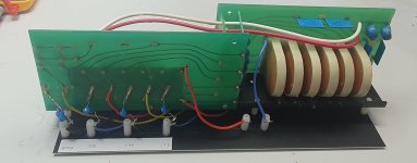
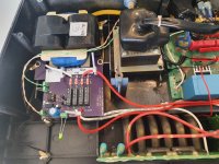
Update. I've been listening to the direct drive amps for some time now, and it's time to do some serious measurements.
I build a dummy load out of the delay line section of an ESL63 and some capacitances to emulate the panel capacitances, see pic.
To my surprise, small ceramic caps rated for 6kV are common and low cost.
The measurement shows the impedance of the dummy load over frequency. Over most of the audio band it hoovers around 300k, but the phase goes through major changes.
This dummy load doesn't take into account the air load on the diaphragm, among other things.
Do you guys think that this would make a major difference, and if so, is there an easy way to include that with some more parts?
Jan
Attachments
Hi Jan,Update. I've been listening to the direct drive amps for some time now, and it's time to do some serious measurements.
I build a dummy load out of the delay line section of an ESL63 and some capacitances to emulate the panel capacitances, see pic.
To my surprise, small ceramic caps rated for 6kV are common and low cost.
The measurement shows the impedance of the dummy load over frequency. Over most of the audio band it hoovers around 300k, but the phase goes through major changes.
This dummy load doesn't take into account the air load on the diaphragm, among other things.
Do you guys think that this would make a major difference, and if so, is there an easy way to include that with some more parts?
Jan
What exactly is it what you are aiming at and why using a dummy instead if the complete ESL ?
Hans
I hate the noise and the 'whoop, whoop, ... 😎
Measuring my amps with a somewhat representative load.
Jan
Measuring my amps with a somewhat representative load.
Jan
I doubt that ferroelectric capacitors are a good representation due to nonlinearity and hysteresis. Use teflon/PP film caps instead. With some effort one may obtain air caps used for RF tuning.somewhat representative load
As with series LC tank, series R could represent active load per say or would it?
Aww, didn't think about that.
But the ESLs themselves also have ceramic caps.
If that speaker and/or the additional caps represent a non-linear load, it might not be that bad, if the Rout of the amp is sufficiently low.
Isn't it a bit similar with a 'normal' speaker, that is a quite non-linear load, but still allows low distortion from the amp.
When I get to it, I can compare the amp distortion with the dummy load and a 300k resistor.
Jan
Insert a series resistor so you can see the current and measure its distortion. Those caps are pretty bad BUT it would be a good stress test of the amp. You may be putting more current through the caps than they can handle. probably should put them in a box. We found all manner of parts that could not handle surges during surge testing. Some had catastrophic fails. I would fuse the amp output. It would be a shame to reduce it to char if a cap arcs and shorts.

Cap upgrades for the ESL's do make a difference. Its not an easy part to source or create. We made them from "teflon" PCBs for the small ones and sourced a film cap for the large ones.
The amp is short-circuit proof by design, so that wouldn't be a problem.
I'm not sure what the rating is for the caps on the delay line chains, but mine are 6kV, and will never see more than 4.4kV.
So there is some margin.
I know of at least one outfit that builds their own caps, I think they use blank PCB material and double side copper foil cover, then immerse the thing in wax.
I just did a quick check at Mouser for 6kV film caps. Smallest value they had were 470pF WIMAs, not expensive, but huge in size (pitch 22.5mm).
Jan
Is this 6kVDC? or 6kVAC rating. With ceramics, usually the AC rating is based on the peak-to-peak not exceeding the VDC rating; VAC = VDC/(2*sqrt(2))To my surprise, small ceramic caps rated for 6kV are common and low cost.
So if rating is 6kVDC, the AC rating is likely about 2.1kVAC. Probably only a concern if driven long term, but something to be aware of.
https://www.psma.com/sites/default/...ac-parameters-dc-rated-ceramic-capacitors.pdf
The airload will not make a major difference, mainly because the transduction coefficient of the ESL is so small.This dummy load doesn't take into account the air load on the diaphragm, among other things.
Do you guys think that this would make a major difference, and if so, is there an easy way to include that with some more parts?
At mid and high frequencies where the radiation impedance(ie airload) is resistive, its contribution to the electrical impedance would be well approximated by a 25Meg resistance in parallel with the ~300K of the electrical network...an insignificant difference.
https://www.diyaudio.com/community/threads/driving-the-beveridge-esl.381885/post-6924634
https://www.diyaudio.com/community/threads/electrostats-vs-conventional-drivers.17424/post-6957351
At low frequencies where the impedance of the electrical network rises toward 10Meg, you will see a small difference from the airload mass and mechanical stiffness of the diaphragm suspension. I think I had previously provided you these approximate component values for putting in parallel with the electrical network to evaluate the difference. I don't think this difference is anything worth pursuing.

Thanks again to Hans Polak for continuing to refine his ESL63 model. Here is an overlay between the model and your measurements.

Thanks Steve, that's very helpful. Apologies if I asked for what has been given before; my memory isn't too reliable apparently at this age.
The max pk-pk voltage across the caps is 4.4kV and the 6kV rating is a DC rating, so I feel it's OK.
Yes, Hans' model is uncanny close to what I measured.
What puzzles me though is that his curve shows the same 50Hz mains wiggle as my measurement (we're both in 50Hz land).
Are we sure that 'the Hans curve' is from simulation and not also a measurement? Hans?
Jan
Would have helped if I included a plot legend.What puzzles me though is that his curve shows the same 50Hz mains wiggle as my measurement (we're both in 50Hz land).
Are we sure that 'the Hans curve' is from simulation and not also a measurement? Hans?
The blue curve(without any wiggles near 50Hz) is the curve using Hans model as he posted it.
The green curve(with wiggle near 50Hz and offset below 50Hz) is the curve when the LF airload and diaphragm stiffness are included.
BTW, you can measure this effect of the diaphragm resonance on the impedance by measuring an ESL assembly once with the diaphragm unpolarized, and once with it polarized. The transduction coefficient will be zero when ESL is unpolarized, so you will get a smooth line. Turn on the polarizing voltage, and the motion of the diaphragm will be reflected in the impedance measurement.
More details on this are contained in the Baxandall ESL chapter. Here is one relevant figure from it.

I need to test this but I believe an inpolarized speaker will still generate sound at 2x the input frequency. I know that is true for single ended transducers.
Thanks Stephen. So it is just a coincidence that this wiggle falls on our European mains frequency!Would have helped if I included a plot legend.
The blue curve(without any wiggles near 50Hz) is the curve using Hans model as he posted it.
The green curve(with wiggle near 50Hz and offset below 50Hz) is the curve when the LF airload and diaphragm stiffness are included.
BTW, you can measure this effect of the diaphragm resonance on the impedance by measuring an ESL assembly once with the diaphragm unpolarized, and once with it polarized. The transduction coefficient will be zero when ESL is unpolarized, so you will get a smooth line. Turn on the polarizing voltage, and the motion of the diaphragm will be reflected in the impedance measurement.
More details on this are contained in the Baxandall ESL chapter. Here is one relevant figure from it.
View attachment 1087953
I'll read the Bax chapter again, it's been a while.
Jan
Another step forward.
I am working on the following setup: streamer (Volumio Primo) into a miniDSP Flex with Dirac Live! enabled, into the two stereo DACs of an ADI-2 Pro Fs R.
The Flex has 4 configuable outputs, so one stereo pair goes to the ADI for the DAC that feeds the direct drive amp, and another stereo pair to the DAC that feeds a 'normal' amp that drives the step-ups.
I can switch inside the speaker (IR control) which signal is fed to the stators, direct or from step-up.
So far this all works as advertised.
To prepare for the Dirac runs I intended to equalize the freq response and level of the direct drive and the step-up output at the panel. That way, the speaker level and response is the same whatever the drive selection, and the Dirac room correction would be valid for either drive method.
Attached are the freq response curves; please ignore the average level differences for now.
Two comments:
- that step-up and its networks manipulates the flat amplifer response;
- the direct drive looks good except for some low end bump.
Now, all of this is easily matched with the Flex DSP, but I wonder: do I match the direct drive to the others, or vice versa???
Jan
Note: the two dips are at 158Hz and 632Hz (factor of 4 - why?).
Attachments

Last edited:
Jan,Another step forward.
I am working on the following setup: streamer (Volumio Primo) into a miniDSP Flex with Dirac Live! enabled, into the two stereo DACs of an ADI-2 Pro Fs R.
The Flex has 4 configuable outputs, so one stereo pair goes to the ADI for the DAC that feeds the direct drive amp, and another stereo pair to the DAC that feeds a 'normal' amp that drives the step-ups.
I can switch inside the speaker (IR control) which signal is fed to the stators, direct or from step-up.
So far this all works as advertised.
To prepare for the Dirac runs I intended to equalize the freq response and level of the direct drive and the step-up output at the panel. That way, the speaker level and response is the same whatever the drive selection, and the Dirac room correction would be valid for either drive method.
Attached are the freq response curves; please ignore the average level differences for now.
Two comments:
- that step-up and its networks manipulates the flat amplifer response;
- the direct drive looks good except for some low end bump.
Now, all of this is easily matched with the Flex DSP, but I wonder: do I match the direct drive to the others, or vice versa???
Jan
Note: the two dips are at 158Hz and 632Hz (factor of 4 - why?).
Good to see that you are still working on your direct drive amp with enthousiasm.
If you allow me, in your mail you give a lot of info’s that need some extra detail.
1) When you talk about “step-up” I assume you mean using the Quad’s transformer, but is this with the dual trafo setup including the 3 resistors and the 2 caps or is it just one transformer section.
2) the frequency responses that you show are all taken from your attenuator connected to the HV side, right ?
3) The blue line in this case shows the direct driven FR. I wonder where the 5dB lift between 40 and 60 Hz comes from or is this by purpose ?
4) Then with Dirac Life you have processed the direct drive signal (paX) to match the version through the step-up transformer driven by a purify amp (purify), true ?
5) If “Purify” is indeed the signal through the step-up transformer, I’m rather amazed by its shape including the two dips.
6) So, what was the load on the HV side in both cases ?
Hans
Hi Hans,
I have measured indeed directly on the wiring going to the stators.
The graphs are the freq response measured at the stators, on the speaker, so the load was the actual speaker.
No Dirac processing yet, just a flat signal sweep into either the direct drive or Putzeys' Purify amp and my own paX solid state amp.
I use sets of HV relays to switch the stator leads to the output of the transformer set, or to the output of the DD amp.
No mods on the low voltage input and transformers, so all parts on the primary and secondary are untouched.
I don't know where the 5dB lift on the direct drive comes from, I need to investigate.
You see a similar lift but more pronounced with the low voltage amps through the stepup transformers.
So it is a simple direct comparison on the stators, using either a direct drive amp, or using the stock stepup xfrmrs and their primary and secondary networks.
I have no idea where the two dips come from. I noted that their ratio is pretty perfect factor of 4.
A long shot - assume a resonance circuit in one xfrmr circuit, would that cause a 4x freq resonance on two transformers?
Jan
Attachments
- Home
- Loudspeakers
- Planars & Exotics
- Driving the Beveridge ESL