It's 'just' engineering. Throw enough money at it and pretty much everything is possible ;-)
But I don't see that the problems with an analog solid state amp magically disappear by making it class D.
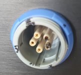
BTW I just found out the hard way that you should not leave high voltage connectors open ended. The mating plug construction is an integral part of the isolation.
Jan
But I don't see that the problems with an analog solid state amp magically disappear by making it class D.
BTW I just found out the hard way that you should not leave high voltage connectors open ended. The mating plug construction is an integral part of the isolation.
Jan
Attachments
Actually, it might not be a bad idea, if you can get those high voltage FETs or IGBTs to switch fast enough.Could eventually a class D design be teached to output some 2kV? Still fitting into an average base of an average ESL?
They are optimized for switching.
There would probably still be significant losses.
Jan
The EMI with 8 KV peak to peak at 60+ KHz would be really challenging. Maybe a switching amp driving a transformer with feedback from the secondary.

A feedback loop around the transformer (the good ol analogue way) has been on my mind some times...
A voltage divider at the secondary, or maybe better a series resistor and apply current feedback.
Doable... maybe the phase shift is to large at high frequency?
Below 100Hz i dont play since i go active.
A voltage divider at the secondary, or maybe better a series resistor and apply current feedback.
Doable... maybe the phase shift is to large at high frequency?
Below 100Hz i dont play since i go active.
If we knew the transfer function of the transformer and assume that the transfer function is somewhat stable over the listening range.
Then we could model that and compensate with 180deg phase shifted harmonics in a DSP in the preamplifier stage.
I know that they use this trick in subwoofers, and they can reduce the distortion with 20dB. More complicated but doable would be to model it over a wide range of amplitudes in the DSP...
Then we could model that and compensate with 180deg phase shifted harmonics in a DSP in the preamplifier stage.
I know that they use this trick in subwoofers, and they can reduce the distortion with 20dB. More complicated but doable would be to model it over a wide range of amplitudes in the DSP...
Back to Jan's direct drive. It seems this is a single ended class A design. The least efficient amp possible. Since the the load is by definition AC coupled (no DC though this cap) you could cut the idle power consumption by a lot by driving the positive and negative circuits, instead of using the positive side as a current source. AC coupling the drive signals should not be an issue. Turn on/off transients will of course be an issue.
Current feedback with the transformer would be great. There are two transformers so the ground referenced sides are accessable. Another alternative is the AP transformer drive which is known to work quite well : https://patents.google.com/patent/US4614914A/en
Current feedback with the transformer would be great. There are two transformers so the ground referenced sides are accessable. Another alternative is the AP transformer drive which is known to work quite well : https://patents.google.com/patent/US4614914A/en
Yes Demian, it's class A but note that the current source load is dynamically driven (the Nelson Pass method) so the efficiency is almost double what a pure class A would be. But class AB would of course be better.
My initial idea was to place a class AB output stage after the current design (throttled down) so I could drive up to 100mA or more into non-segmented, pure capacitance speakers like the Martin Logans.
Just haven't got around to it, and my current priority is to double the output voltage so the ESL 63's can be driven to full output.
Jan
You may be interested to know that different manufacturers actually do use different definitions for PEQ filters. I noticed this when comparing MiniDSP and Hypex responses.PEQ data is frequency and slope and filter order. It defines the eq.
How can that differ from manu to manu?
Its like saying that buying 2 + 2 items gets you a different number of items from different manufacturers.
For example, if you put in a PEQ filter with Q=1 and gain = +5dB to both, you will notice that the responses are different.
You have to use Q=1.33 in the Hypex to get the responses to match.

Additionally, if you look at a trend of increasing boost, you will see that MiniDSP holds the -3dB bandwidth constant, but Hypex does not.
Instead you will see the shape of the central peak and slope transition to be constant.


More information on these 2 different definitions for Q can be found here:
https://www.andyc.diy-audio-engineering.org/parametric-eq-parameters/index.html
https://www.andyc.diy-audio-engineering.org/parametric-eq-parameters/parametric-eq-parameters-2.html
https://www.andyc.diy-audio-engineering.org/parametric-eq-parameters/parametric-eq-parameters-3.html
Using the Qb and Qm naming convention in links above:
Qb = Qm/sqrt(gain) for gain >= 1
Qb = Qm*sqrt(gain) for gain < 1
The following products use Qb:
MiniDSP
Behringer iNuke DSP
REW
The following products use Qm:
Hypex
Behringer DCX2496
Multi-Sub Optimizer
FIR Creator
Maybe it is just me, but I found it humorous that Behringer used different Q definitions for different products.
- Home
- Loudspeakers
- Planars & Exotics
- Driving the Beveridge ESL