That's - impressive! I went for the original Gradients as they blend so well estetically, and with Peter Walker's blessing I expect acoustically as well.
We'll see.
Jan
We'll see.
Jan
By linearly do you mean frequency response or distortion? The big FETs have a "nasty" cap transition point. You really need a pretty good driver to get them to perform. The gate current needed increases abruptly as the drive increases.Alex, can you share a schematic?
I've tried something like that but had issues to get it to work linearly at higher frequencies due to the MOSFET internal capacitances.
Jan
Both. I probably didn't drive them with enough current capacity.
I then switched to tubes for the output and all was well.
But after the project is finished I intend to get back to those HV MOSFETs (I also used the 4.5kV from IXYS), I hate to admit defeat.
The other thing was the Spirito effect, sort of 2nd breakdown equivalent in MOSFETs; these devices are not really designed for linear operation where high voltage and appreciable current can occur at the same time. Their linear SOA is pretty much non-existing.
I'd appreciate your thoughts/experiences on this, on a PM if you wish.
Jan
Last edited:
I don't have experience with the high voltage FETs. However the insulated gate fets all have a threshold where the gate capacitance increases rapidly. You need enough drive to dump the needed charge into that gate. Add a gate resistor and you get a current limiting into that node making things more complicated. What I did for the FET output amps was work back from the peak current required for the load and then peak current to turn on the fet etc. I always had drivers for FETs which were smaller versions of the same. The vertical fets are more abrupt and faster so harder still to make stable. I remember blowing some when they were first available. No sound at the speaker but the vendor said all the bonding wires inside had vaporized (in microseconds). I had to get better on dealing with stability and current limiting to get past that roadblock. This was 40 years ago.
Sure. Later. Getting old it seems. Early days I could prototype the whole unit without drawing a line.Alex, can you share a schematic?
I've tried something like that but had issues to get it to work linearly at higher frequencies due to the MOSFET internal capacitances.
Jan
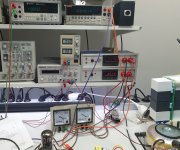
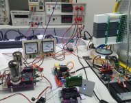
Just a sample of progress: Verified the offset servo at full supply level (~+/-2.1kV).
The meter in the top left corner of nr4offsetlevel shows the output offset. Yes that's 0.92mV ;-)
The square meters show the bias current, 30mA full scale, currently at 13mA design center.
I have 6 amps in various stages of completion. A few of them have been playing on the Quad 989 already.
The enclosures are ready and partly wired, waiting for the final PCB for the power sequencing (had to change a DC-DC converter which didn't fit the original PCB). Umbilical cables between amp and speaker are done.
All should be up and running end of August, after my short trip abroad.
Looking forward to closing a multi-year project!
(I know someone who will call it a multi-decade project ...).
Jan
Attachments

Jan, for your future experiments I think it would be worth to contemplate a nice triodic FET something like LU1014 (it's obsolete but still available and a pretty nice device for a one off project) as a driver and cascode it with a HV device, that way you get a much easier and nicer input capacitance as well to drive.
This could probably be done with tubes as cascodes too.
If I recall it correctly, many HV FET's have a violent Cgd kink roughly at some hundred or so Vds which increases abruptly when moving towards 0 Vds, but if you don't drive near full swing it shouldn't be of a great concern.
With regards to Spirito.. I am not really acquainted with how electrostats are driven, but isn't the drive voltage at rest, ie. no music, somewhere in the middle between 0 and max drive voltage? What I'm thinking here is, when at rest there's not much DC current at all except perhaps the leakage current in the electrostats, although I don't know how much would be.
Secondly, me guessing again, electrostats don't run down to deep 20 Hz, so an additional HP filter at some hundreds of Hz could ensure we don't tease Spirito too much as it's important to keep the cycles as short as possible, ie. as high frequency as possible as that mitigates the local thermal runaway in the FET cell structure, so keeping the HP filter at as high frequency as possible is important, DSP filter helps as it can be made much steeper too.
Just some thoughts.
Actually I am driving the tubes in common grid, sort of cascoded.
And as far as Sprito is concerned, you may well be right. In fact the choice is between a low current HV FET with a current capability of say 1A, and a massive IGBT with a 30A current capability. The latter may be insensitive to low current Spirito effect, but has huge non-linear capacitances.
The first type has much lower capacitances but probably more sensitive to Spirito.
I have a vague plan to replace the tubes in my current HV amplifier design with FETs or IGBTs to see how that works out, after I have finished this project.
Jan
Ok, I just remember vaguely the Spirito talk over 4 years ago, back then there were very few HV FET candidates that existed on the market as far as I looked around and didn't seem all too promising wrt Spirito, and they aren't cheap either, or weren't... let's hope there are or will be better devices in a near future, something like new HV GaN FETs.
Looking forward to the day you get it running, it will be something to behold!
Looking forward to the day you get it running, it will be something to behold!
:)Question: does anybody have measurement data for the ESL63 step-up transformers? Things like induction, coupling, stray induction/capacitance etc?
I would like to build a model of it for LTspice.
Jan
I would like to build a model of it for LTspice.
Jan
Hi Jan,Question: does anybody have measurement data for the ESL63 step-up transformers? Things like induction, coupling, stray induction/capacitance etc?
I would like to build a model of it for LTspice.
Jan
To my feeling what you ask is completely covered in my model.
Its not an 1:n ratio model with coupling losses, but a much more elaborated model with B and H parameters, induction, stray capacitance and the lot.
Hans
I think that's all in Hans' model already: https://www.diyaudio.com/community/...ay-line-inductors.338927/page-22#post-6710863 I do remember taking measurements but that seems pre-covid so like maybe 100 years ago. . . (Hans beat me to the reply)Question: does anybody have measurement data for the ESL63 step-up transformers? Things like induction, coupling, stray induction/capacitance etc?
I would like to build a model of it for LTspice.
Jan
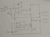
Thanks Alex, food for thought! I assume the load is between the tap on the floating supplies and ground.
20mA seems like a sweet spot; I'm running mine (tube based, different schematic) at 13mA.
Jan
20mA seems like a sweet spot; I'm running mine (tube based, different schematic) at 13mA.
Jan
Well. I needed 10 mA, capacitive load, basically connection cable, about 10 kc max.
There's an error in circuit as drawn. You should swap inv and non-inv inputs at top O/A.
Getting old.

There's an error in circuit as drawn. You should swap inv and non-inv inputs at top O/A.
Getting old.
Last edited:
Yes, the cables are an important part of the load. I made up some 3 ft umbilicals and managed to keep the parasitics to about 30pF.
Somebody gave me 3m HV coax cables terminated with HV BNC connectors, very nice cables, but 250pF ...
Jan
Somebody gave me 3m HV coax cables terminated with HV BNC connectors, very nice cables, but 250pF ...
Jan
- Home
- Loudspeakers
- Planars & Exotics
- Driving the Beveridge ESL