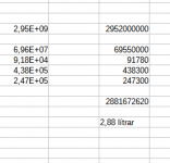
To get the volume within Fusion, you can model the inner space (roughly) and get it's volume I suppose. At least I think Fusion can do the calculation of volume for solids. To get it even more precise you could subtract the driver + enclosure from a solid as big as the two together. That's what I used to get my numbers.
I am surprisingly dull at times. Obviously I have the volume of all the items used for the build. It never occurred to me to simply subtract them from a solid extrusion of the final shape. The results are that my current design is at some 2,88 liters when the drivers are included.
edit: 2,88l * 25 = 72 liters total volume each.
Attachments
There are many attributes of my speaker design that could apply to me aswell; thick, dense, simple. 🙂Thick? :-D
//
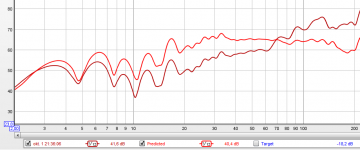
I got a bit of free time tonight. I made myself useful by setting up my UMIK-1 on my desk and installing REW + Equalizer APO. This is actually the perfect test environment, because I have the worst speakers known to man as my lab rats; logitech desktop speakers + sub.
This is the first time I have used any of this so I did not expect any results at all to begin with. To my surprise... I spent about 30 minutes setting up a filter (mostly from 20hz - 300hz) and it is just unbelievable how easily I can make these horrible speakers sound... less horrible! The little tweak I did created a sound stage and voices sound almost like voices. Compared to how it sounded an hour ago, this is quite simply astonishing. Obviously there is nothing going on below... 40hz or so, don't know what the mic was picking up.
I have set up the computer I will dedicate to the 25s. I have an old i7 with about 16 megs of ram and a SSD in a very nice HP workstation enclosure. It is quite silent and with a quick test of the USB ports it seems it will do quite nicely. With it I will be using a second generation Apple Cinema LCD screen, so I will look cool to accidental time travelers from the past. I have a working copy of JRiver I bought back in the day, but I think I will get the newest version.
Still no response from either of the CNC shops. However I have a meeting next Wednesday in a workshop not 500 meters from my house. I had no idea.
(Music is still playing while I am writing this and I have yet to plug my ears with anything found within reach. Which means the small bit of EQ-ing I did worked wonders.)
Attachments
Last edited:
Thanks. I had seen something about it and it looked interesting. Have you tried it out?
p.s. Är du den samma TNT som var på Prisjakt på början av tvåtusend talet?
p.s. Är du den samma TNT som var på Prisjakt på början av tvåtusend talet?
Approximately 400 meters from my home, there is a CNC machine I can use. Since non of the businesses specializing in manufacturing are interested, it seems I must do everything myself. This means I will have to simplify the design. Dumb it down, if you will. It is 3d capable, but I would be pushing my luck, keeping it occupied for long periods.
I am not very happy about this, but at least there will be some progress.
I have opted for a simple box shape.
Now, I have the option of using MDF, Masonite or plywood. What should I chose and why (price is quite similar - the quality of plywood is unknown)?
I am not very happy about this, but at least there will be some progress.
I have opted for a simple box shape.
Now, I have the option of using MDF, Masonite or plywood. What should I chose and why (price is quite similar - the quality of plywood is unknown)?
If you can, still include elaborate roundovers on the sides of the front baffle 🙂.
That should be simple and not too time consuming.
I picked the genuine Baltic Birch ply, for several reasons. I wanted my construction to be serviceable for one. It is cleaner to work with (it contains a lot less toxic glue, but still enough to wear protection) and I do expect it to have an audible advantage, though that is debatable. The rigidness of the material for serviceability was my prime reason.
I have coated it with epoxy, changing it's behaviour and have many braces build in.
So maybe I'm not the best example. I do genuinely believe the roundovers do help, just look at the horn threads and the recent talk of Torus shapes for open baffles show little things like sharp edges do have a life of their own in audio due to having more diffraction.
Maybe you can incorporate the use of something like quarter round stock material into the design? Something like this: QR-M106-8 Perfect Match MDF Moldings Quarter Round N/A | FinishBuild (R)
(I didn't look for specific sizes but this type of stock material should be available)
(I didn't look for specific sizes but this type of stock material should be available)
Interesting, maybe that's possible. I hope I will find some solution. I will have a think about things. Perhaps all is not lost.
I have also started to think about wiring; connections etc. I dislike soldered connections, unless done to perfection, so I was thinking about cramping the wires on the drivers. I am currently working on a pair of old Dali speakers (with Vifa paper cone drivers). With only 8 drivers to solder, I quickly decided not to.
My current shopping list looks something like this; feel free to comment. (I know the crimps are of different sizes, but it seems that is the case with the driver terminals - am I going mad?)
0.110" (22-18) Fully Insulated Female Disconnect Red 10 Pcs.
3/16" (16-14) Fully Insulated Female Disconnect Blue 10 Pcs.
JSC Wire 16 AWG Red Primary Hook Up Wire 100 ft. USA
JSC Wire 16 AWG Black Hook Up Primary Wire 100 ft. USA
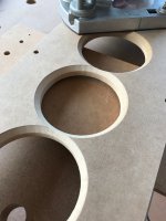
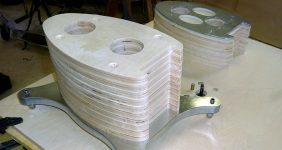
I did the chamfering on the back of the baffle myself and on the edges of the front baffle as it was easy enough to do and saved quite a bit of money on CNC cost. Using a roundover or chamfer bit following along an already cut path is fairly easy.

I used a 9mm divider but I did not dado it into the front panel just used some silicone type glue on the edges when I glued the baffle on. The dividers are really good at keeping the structure rigid.
I would not use separate chambers for the drivers if I was to build again. I think it is actually better when wired series parallel to just let it all be in one volume or closer to that than what I did.
For driver fixing I used superglue in the screw holes to harden them and that worked fairly well. If I was to do it again I would drill the hole as deep as possible without coming out the other side and fill it with epoxy to screw into that.
The frame of the TC9 can easily be warped with too much screw or bolt pressure.
Attachments
No not going mad the positive and negative terminals are different sizes. I really hate those insulated terminals. Uninsulated terminals and crimp tool available from any auto parts store gives a much more secure bond where the crimp bites into the wire insulation rather than just being forced flat onto the wire through pressure.I have also started to think about wiring; connections etc. I dislike soldered connections, unless done to perfection, so I was thinking about cramping the wires on the drivers.
My current shopping list looks something like this; feel free to comment. (I know the crimps are of different sizes, but it seems that is the case with the driver terminals - am I going mad?)
You can also buy clear insulating shrouds from China that slip on the wire before the crimping and then slide back over if you feel than insulation is needed inside a speaker or just heatshrink.
The uninsulated terminals are available from RS, element14, Mouser, Digikey etc.
Thank you fluid. I obviously took much inspiration from your build, even though it is on the opposite side of the globe. It was a simple matter of rotating everything 180°.
Regarding the separate vs single chamber; can you elaborate a bit? Is it a impedance issue? It would obviously make everything a lot easier, even allowing for more dampening bracing. Most people seem to have at least each series in a separate chamber; do you find that to be unnecessary as well?
Well, doing the chamfering myself would mean I would have to invest in a lot of tools, which I might just do. But a router, bits, etc. will most likely be more expensive over here than other budgetary item. As I recently moved into an old wooden house, that might actually be a useful thing to have anyways.
I have no real reason to use the insulated crimps, except for those very unlikely situations where a wire would come lose or... I don't know. This is good advice, I will purchase the normal ones.
Ha, well my cabinet is symmetrical so it lends itself to that, but having the base at the top presents an installation challenge 🙂It was a simple matter of rotating everything 180°.
The TC9 is a pretty consistent driver but there are differences. I found that when I had 5 in a separate chamber the way the impedance peaks aggregated together was better when the drivers were sorted so they balanced out. Having them all in the same chamber balances them out. I don't know about separate ones per driver I suspect that is better than 5 in a box.Regarding the separate vs single chamber; can you elaborate a bit? Is it a impedance issue? It would obviously make everything a lot easier, even allowing for more dampening bracing. Most people seem to have at least each series in a separate chamber; do you find that to be unnecessary as well?
The stiffness of the ribs is useful, full acoustic isolation I don't think is.
As to the tools it's up to you just don't waste your money on rubbish unless you only need it for one job. It's always more expensive in the long run to have to buy the tool twice.
That, I did find out... I bought a cheap router and good quality bits, figuring that would get me through my build. The router lasted a week before the bearings were shot. I immediately bought a better router (brand: Makita, 1850 watt, single speed 22000 rpm) and that survived all I could throw at it. I've been using it ever since for all kind of duties. It even survived using it to machine 10 mm thickness aluminium baffles...
For that I did need to reduce the speed.
For that I did need to reduce the speed.
Fluid, thanks - yeah, the physical interactions of all those drivers might be better in someways than having them work in decoupled environments - it makes sense it could smooth things a bit.
Wesayso, the Makita I think you are talking about costs around 600 euros over here and barely 300 dollars on Amazon. It's the Makita RP1800. How easy is it to operate? Would I need to practice for months or years?
Funny how things quickly turn around. I am now leaning towards bent plywood for the sides, having only the baffle CNC'd and doing more of everything else by myself. Perhaps I will make a simple design tonight.
I found it very easy to operate as I have it upside down in a table. The table simply is a Black and Decker workmate with a big piece of ply on top of it. With the copy bits (the ones with roller bearing on top) I could do everything that I needed to do.

In this picture you see one of the router bits sticking out. The bolt with rings behind it was used to make soft starts easier. The router was mounted upside down and I used the guide system that came with it to bolt it to the piece of ply I used as my table. Simple, cheap and effective.
In this picture you see one of the router bits sticking out. The bolt with rings behind it was used to make soft starts easier. The router was mounted upside down and I used the guide system that came with it to bolt it to the piece of ply I used as my table. Simple, cheap and effective.
Attachments
I did purchase a cheap router, along with some other tools. Waiting on delivery. I will have many uses for this tool, so I thought it would be good to practice using a cheap one. In other news I have decided to use sheep's wool for absorption. In theory, wool is cheap in Iceland. In practice, it is inexpensive enough for me to ben interested.
One of the articles I found interesting: Characterization of Sheep Wool as a Sustainable Material for Acoustic Applications
I did some work on a pair of "rescue-speakers" I had. It made me remember a few things. First, I do not have a lot of time. Second, I really like taking things apart and putting them together again. Third, I am unable to put things together correctly. Fourth, I am an audio snob who cannot enjoy reasonably priced loudspeakers. Fifth, there is a reason Icelandic winter played the role of Winter with a capital W in GoT.
- Home
- Loudspeakers
- Full Range
- Drengur's build: Langanes 25 - Line arrays