Hello there.
Inspired by Wesayso, Halair, Fluid, Koldby, Nojak, Nvphotos, TNT and others. I decided to do my own Line Arrays... "with blackjack and hookers" as Bender would have put it. In many ways I am the worst example of someone who should DIY; I have no patience, no skills and am quite prone to mistakes. But, I do get obsessed over things and tend to not let go of those things until I have quenched my thirst. I am currently obsessed over line arrays, which is on top of my live-long obsession over "sound".
But why floor to ceiling line arrays? The reasons are quite many, but my experience has taught me a lot about what I dislike in loudspeakers and what I hate about loudspeaker marketing. So, what a better start to a project than to be influenced primarily by negative feelings? On the positive side, it seems to me that Mr. Russel, struck gold with his development of the IDS-25s, and the trials and errors of the people on this forum, mentioned above, have made me come to believe that the principles of F2CLA's are as close to perfection as money can buy, for me and my preferences.
First of all I wanted to make this thread to simply catalog what I had done, and how I did it - and who was to thank. But then I thought. Wouldn't it be best to simply get advice as I go. My ego will take a bit of bruising, but I am sure the end results will be worth it. I am two years away from having made the decision to do this, and probably a couple of years away from being "done" with building. So this will be a slow-moving project.
So; the decisions I have taken so far:
I am open to suggestions or comments about these decisions.
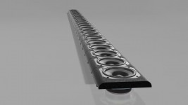
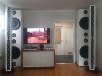
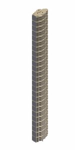
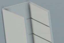
My first front-panel rendering is attached as proof of my intentions, but there are many things yet undecided.
...to be continued.
There is one thing to keep in mind. I am based of a barely habitable island in the middle of the North-Atlantic. So, in some ways I am in a similar boat as those Australians and New Zealander's on this forum in that getting supplies can be tricky and expensive - so many of the choices I will make are simply because of that particular hurdle; not everything is available or affordable over here.
So if any of you have any input or warnings, I would be happy to hear them. I have read through all the big Line Array build threads several times, and will continue to do so regularly. I know some stuff, but there's a lot of stuff I don't know - I won't get upset about any questions or statements. I have some background in home audio, and I am a strict science-first kind of person and don't like chasing myths - but I am happy to discuss myths and snake-oil.
Inspired by Wesayso, Halair, Fluid, Koldby, Nojak, Nvphotos, TNT and others. I decided to do my own Line Arrays... "with blackjack and hookers" as Bender would have put it. In many ways I am the worst example of someone who should DIY; I have no patience, no skills and am quite prone to mistakes. But, I do get obsessed over things and tend to not let go of those things until I have quenched my thirst. I am currently obsessed over line arrays, which is on top of my live-long obsession over "sound".
But why floor to ceiling line arrays? The reasons are quite many, but my experience has taught me a lot about what I dislike in loudspeakers and what I hate about loudspeaker marketing. So, what a better start to a project than to be influenced primarily by negative feelings? On the positive side, it seems to me that Mr. Russel, struck gold with his development of the IDS-25s, and the trials and errors of the people on this forum, mentioned above, have made me come to believe that the principles of F2CLA's are as close to perfection as money can buy, for me and my preferences.
First of all I wanted to make this thread to simply catalog what I had done, and how I did it - and who was to thank. But then I thought. Wouldn't it be best to simply get advice as I go. My ego will take a bit of bruising, but I am sure the end results will be worth it. I am two years away from having made the decision to do this, and probably a couple of years away from being "done" with building. So this will be a slow-moving project.
So; the decisions I have taken so far:
- 1. I will build a pair of IDS-25 clones - or some similarity thereof.
- 2. I will use the TC9FD-18-08 - I am sitting on 60 pcs.
- 3. I will use MDF. I had done some sketches using 19mm - but perhaps that is overkill?
- 4. I will design the things in Fusion 360 - and have begun to make myself familiar with the program.
- 5. I will have all the components professionally CNC'd - most likely here in Iceland - depending on price.
- 6. The electronics I will use will most likely be the CAV A20 (2x250w) and I am pondering which sub 1000$ chinese XLR Dac I will buy - but most likely the SONCOZ SGD-1. I will have a computer with Windows (sorry Linux) and the UMIK1.
I am open to suggestions or comments about these decisions.
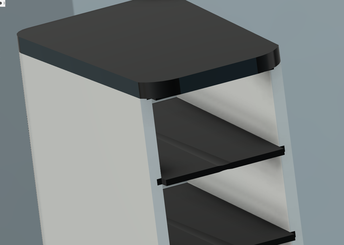
My first front-panel rendering is attached as proof of my intentions, but there are many things yet undecided.
- a. I want a narrow front with sloping edges. Why shouldn't I?
- b. Every speaker will sit in its own chamber. Why is that a bad idea?
- c. I want to avoid screwing the front to the side walls from the front. What should I do?
- d. I am thinking about having a 5-10° angle on the side walls from the front, so that the boxes get more wide towards the back.
- e. I really want the back-side to be somewhat curve-shaped, and removable.
- f. Since I will be using MDF I need good ideas for finishing. I am open to many different ideas.
- g. Since I will be CNC-ing the hell out of those MDF-boards... why not add some kind of artistic expression on the side-walls?
- h. Can I glue everything? Can I screw everything together? What is the optimal approach, what is the worst?
...to be continued.
There is one thing to keep in mind. I am based of a barely habitable island in the middle of the North-Atlantic. So, in some ways I am in a similar boat as those Australians and New Zealander's on this forum in that getting supplies can be tricky and expensive - so many of the choices I will make are simply because of that particular hurdle; not everything is available or affordable over here.
So if any of you have any input or warnings, I would be happy to hear them. I have read through all the big Line Array build threads several times, and will continue to do so regularly. I know some stuff, but there's a lot of stuff I don't know - I won't get upset about any questions or statements. I have some background in home audio, and I am a strict science-first kind of person and don't like chasing myths - but I am happy to discuss myths and snake-oil.
Attachments
Its too much of a struggle when on a mobile though.
I am looking forward to what you have to say. Like I said, we have lots'n'lots of time. When your renovation project is over and you have time, I hope you find your way back to this thread.
I wish you luck with your build, lots of work though.
Thank you. I will surely need luck. Believe it or not, I very much look forward to the work.
Last edited:
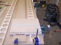
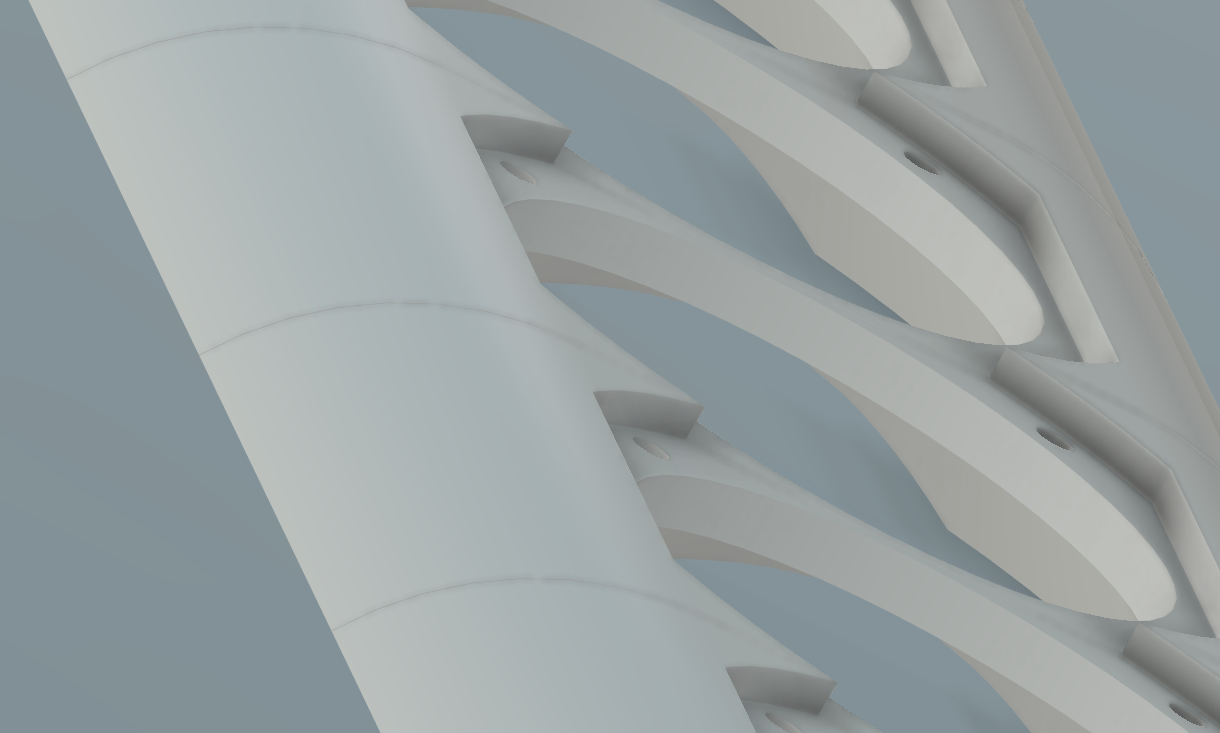
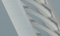
My IDS-24 w/tweeter are "unscrewed" ") , just folded and glued 19mm MDF.
, just folded and glued 19mm MDF.
Separate chambers for each driver secures rigid column and equal pressure profile.
Note the importance of chamfering the rear of midrange holes.
, just folded and glued 19mm MDF.Separate chambers for each driver secures rigid column and equal pressure profile.
Note the importance of chamfering the rear of midrange holes.
Attachments
Last edited:
Very interesting. I might want to go that route - try to limit the amount of screws/nuts.
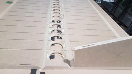
I will also be using 19mm MDF, but I find that chamfering the holes is a bit tricky without hurting the structure of the front - as there is less room on the top and bottom sides, since the drivers will have to stack closely together.
What angle can one get away with?
Wilbur; I see you used a similar overall shape as I was going for. Why did you choose this shape, why did you choose this angle?
The shape: Trapezoidal section allows for target volume (approx 2,7L per unit) and limiting the cabinet depth.....and I like the IDS shape.
Chamfering the holes was not tricky with CNC. The drives are stacked flange to flange. Chambers are divided by 6mm plaster boards glued to the grooves.At least you should chamfer the holes at the sides. Reference is made to Troels' advice.
Chamfering the holes was not tricky with CNC. The drives are stacked flange to flange. Chambers are divided by 6mm plaster boards glued to the grooves.At least you should chamfer the holes at the sides. Reference is made to Troels' advice.
Last edited:
MrKlinky: This is a valid and very common question.
You should take a look at all the different threads regarding full range floor to ceiling Line Arrays - as the solution is pretty much the same with all of them. It is quite manageable today to extend on Russel's equalizer circuit by using computers for processing. It has many added benefits, the foremost of which is that you can adjust all of your DSP to fit the room you are in and (more importantly) your own taste.
I think Wesayso's write-up at the JRiver forums is the easiest detailed introduction.
Why I love JRiver, a tale of taming my Line Arrays
I had thought about perhaps having two types of input on the speakers; one "safe" with basic EQ applied to it so that it could accept any signal without the big change of damaging the drivers, and the second simply to the series-parallel drivers as such - which would be used with my own processing in the beginning of the chain. Now, since I will be the only one using my speakers I will probably not go that way, and I really don't want to do any circuit-work to begin with. I am much more comfortable around computers than soldering irons.
Wilbur: my design has chamfering, but I am not sure it will be enough; I will post a screenshot tonight when I get home.
DSP will have no effect on comb filtering whatsoever - you will still have a horribly variable response with listening position. No matter how pretty and well-built they are, you cannot escape the laws of physics governing driver spacing and upper frequency limit before interference becomes significant. Much effort has gone into the design of plane-wave HF drivers used in large scale PA line arrays for exactly this reason, namely that it is impossible to achieve an even response with widely spaced drivers (in relation to frequency).
Don Keele seems to be the only designer to have made cone-based hifi line source speakers properly with his CBT arrays - this makes for very enlightening reading and viewing!
Don Keele seems to be the only designer to have made cone-based hifi line source speakers properly with his CBT arrays - this makes for very enlightening reading and viewing!
Well. This discussion is bound to happen on each and every thread about line arrays. Comb filtering does exist, yes, but I will not be doing any near field listening, nor will I be jumping up and down, while listening.
My speakers are not meant to escape the laws of physics. They will be made to sound relatively good for what they cost and what they are. For violating physics I mostly play basketball.
I am, as many others around these parts, familiar with Keele's work. I do admire his work, but I am a bit skeptical when it comes to the general assumptions people attribute to him regarding F2C line arrays.
CBT is fine and including except for pin-pointing.
(Water's dog is all over the room too).
We built them all:
- Line source without power tapering
- Line source with power tapering
- Focused line source (parabolic)
- CBT
Every concept got its own strengths and weakness whatever you may dispute with regard to DSP, room treatment, wrong whisky etc. Choose your cake.
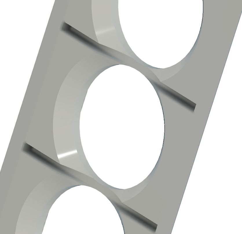
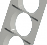
Chamfering
This is what I had in mind to begin with, a 10 degree chamfering from the top.
This has the chamfering starting from 10mm with the full 45° angle. Probably smarter?

This is what I had in mind to begin with, a 10 degree chamfering from the top.
This has the chamfering starting from 10mm with the full 45° angle. Probably smarter?
Attachments

Last edited:
DSP will have no effect on comb filtering whatsoever - you will still have a horribly variable response with listening position. No matter how pretty and well-built they are, you cannot escape the laws of physics governing driver spacing and upper frequency limit before interference becomes significant. Much effort has gone into the design of plane-wave HF drivers used in large scale PA line arrays for exactly this reason, namely that it is impossible to achieve an even response with widely spaced drivers (in relation to frequency).
Don Keele seems to be the only designer to have made cone-based hifi line source speakers properly with his CBT arrays - this makes for very enlightening reading and viewing!
It depends what you call 'properly'. Here, for example, we have what Roger Russell -an excellent engineer and designer of McIntosh's highly respected multiway arrays- has to say on the subject from personal experience:
Why be so overly concerned about comb filtering in column speakers when you probably get this all the time with the speakers y
He provided full design details, including measurements, of both his prototype systems many years ago in AudioXpress. There is also evidence from other acoustic research that indicates that while broad trends in an overall response balance are certainly audible, densely spaced high Q nulls are not especially so on ordinary programme material. We are dealing with matters of degree, not a black & white scenario.
Last edited:
The 45 degree looks better for the driver to breathe. Its close to what I used, save for some space to get bolts and nuts in behind the spokes of the driver. Still not behind a PC, so I can't look up a picture.This is what I had in mind to begin with, a 10 degree chamfering from the top.
This has the chamfering starting from 10mm with the full 45° angle. Probably smarter?

Hello there.
- a. I want a narrow front with sloping edges. Why shouldn't I?
- b. Every speaker will sit in its own chamber. Why is that a bad idea?
- c. I want to avoid screwing the front to the side walls from the front. What should I do?
- d. I am thinking about having a 5-10° angle on the side walls from the front, so that the boxes get more wide towards the back.
- e. I really want the back-side to be somewhat curve-shaped, and removable.
- f. Since I will be using MDF I need good ideas for finishing. I am open to many different ideas.
- g. Since I will be CNC-ing the hell out of those MDF-boards... why not add some kind of artistic expression on the side-walls?
- h. Can I glue everything? Can I screw everything together? What is the optimal approach, what is the worst?
...to be continued.
There is one thing to keep in mind. I am based of a barely habitable island in the middle of the North-Atlantic. So, in some ways I am in a similar boat as those Australians and New Zealander's on this forum in that getting supplies can be tricky and expensive - so many of the choices I will make are simply because of that particular hurdle; not everything is available or affordable over here.
So if any of you have any input or warnings, I would be happy to hear them. I have read through all the big Line Array build threads several times, and will continue to do so regularly. I know some stuff, but there's a lot of stuff I don't know - I won't get upset about any questions or statements. I have some background in home audio, and I am a strict science-first kind of person and don't like chasing myths - but I am happy to discuss myths and snake-oil.
I'm back on a PC, so maybe I can help out a bit...
- a. No problem at all in my view, As I tried to keep my arrays narrow too, preferably as narrow as a human head.
- b. Not a bad idea, but with drivers close together it is challenging to have a divider between the row of speakers. I closed up the chambers for the first ~15 cm from the driver out, but do have holes (at different spots) between those chambers. Closed should work though. I like the idea presented by wilbur-x.
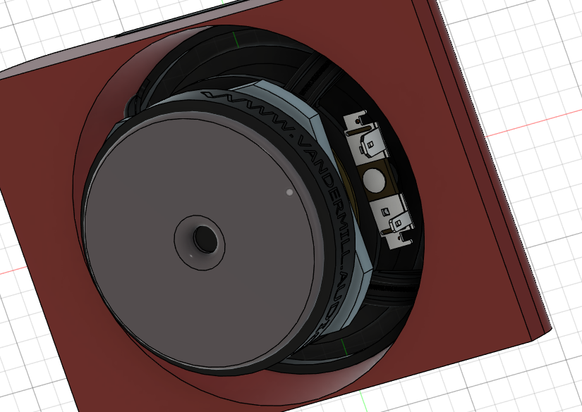
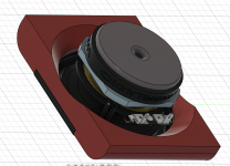
- c. Incorporate threaded holes in the baffle? Mount them from behind? Maybe something like I did for my subwoofer build could work if the baffle is made of 2 pieces glued together... Front baffle design – Vandermill-Audio
- d. As did the IDS-25
- e. A bit harder to construct but doable, using kerfs to be able to bend a panel?
- f. No comments, I picked Birch ply because I like it better as a material to work with. I never considered veneer or something like that. It was either black or the wood itself like I tried to preserve.
- g. Even though I did just that on the side of my subwoofers, for anything playing higher notes (= shorter waves) I wouldn't do it. Even if diffraction would be minimal, it would still be on my mind . I see big round-overs on that front baffle... that I do like. One only needs to browse through Mabat's horn design tool thread to see that a continuous smooth shape out from the drivers p.o.v. would work best.
- h. Yes you can glue everything. Consider using dowels or interlocking panels...

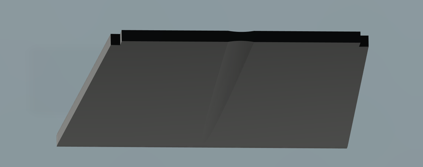
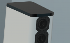
By not chamfering behind the driver spokes you keep more material for the mounting bolts of the driver itself. I had a double aluminium baffle and bolted the drivers to the inner baffle. Here it is in real life:

To get the volume within Fusion, you can model the inner space (roughly) and get it's volume I suppose. At least I think Fusion can do the calculation of volume for solids. To get it even more precise you could subtract the driver + enclosure from a solid as big as the two together. That's what I used to get my numbers. Something like the example in this video should help: Fusion 360 - How to Cut One Body From Another - YouTube
It may even be more simple following this: Quick Tip: Find Internal Volume - YouTube and it also shows how to get the volume.
That way you'd be making a model of the inner air and get it's exact properties.
Attachments
Last edited:
Congratulations on finally getting the PC up and running. All your comments are much appreciated. I am really happy my ideas are not dismissed as idiotic and dumb. Your threaded approach is tempting. One of the few things I have ever designed and built in my life was actually a stereo-rack using... you guessed it, threaded rods. There are many things you say I will have to take into account.
I have actually submitted a design to a couple of CNC-shops (one in the States, one in Iceland (but still 500km from my location)) - just in order to get a rough estimate on the price and whether I have to decrease the complexity of my design. Surprisingly the only feedback I've had for over a month from both of them has been similar: "We'll certainly take a look and get back to you." and "Sorry, we will look at it momentarily."
I decided to use a 2,5° angle - as I thought it looked better and would be slightly easier to work with.

It looks fabulous on paper!

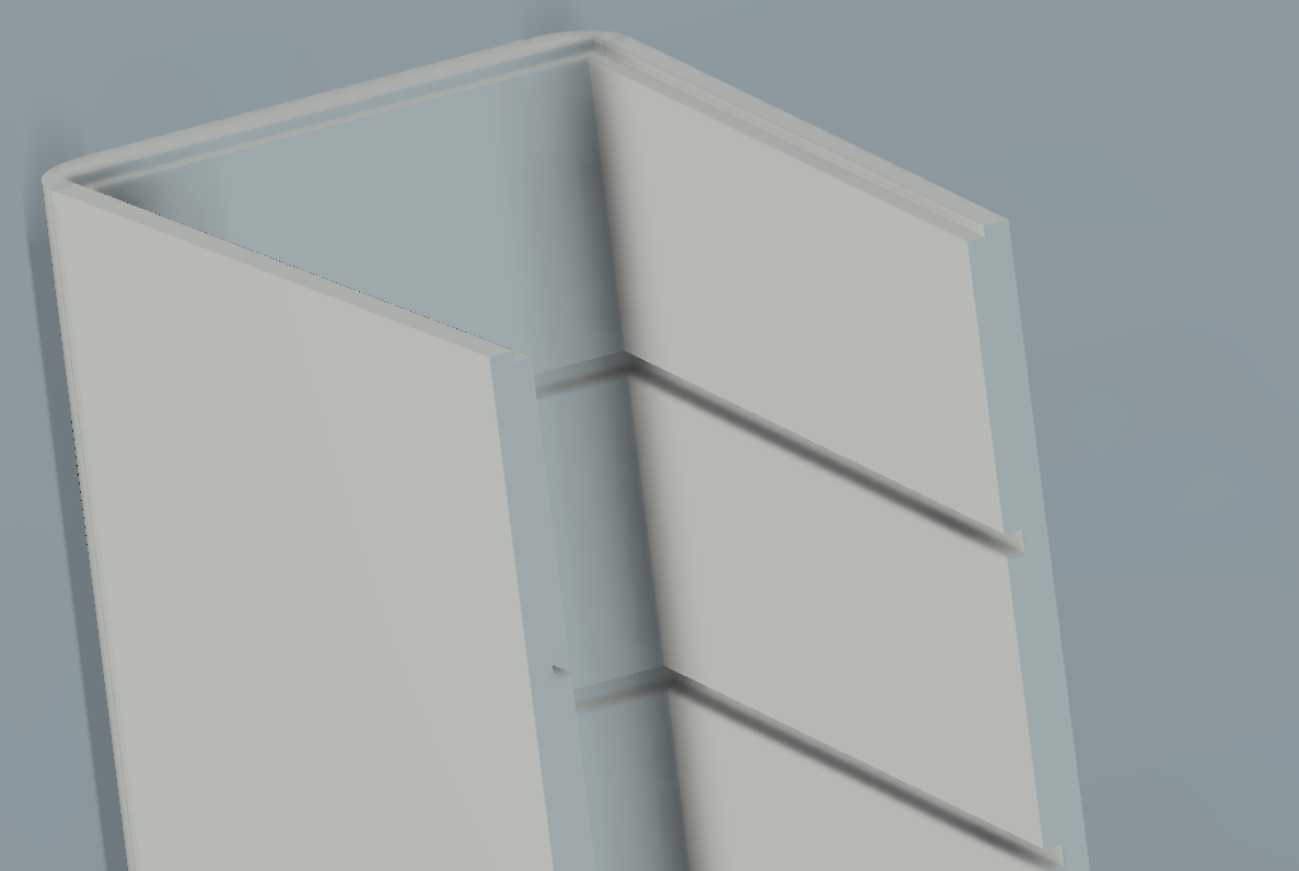
I managed to fit a 6mm divider, but not sure how that will work when building the thing.
The dividers are probably overly complicated, but it just felt wrong not to continue with the curve shape along the top and bottom of the divider...?
As you can see, I kneaded some interlocking into the dough - hoping that would make the assembling easier.
So hopefully everything will fit nicely together if the CNC-fairies are kind enough.
As I am not a particularly smart individual, I had at least 4 designs for the front before I made this one. I trusted non of them to fit the drivers. I the end I simply inverted Wesayso's driver design and slapped it into my panel, subtracting it's shape and then filing the edges. I hope it fits the drivers.
If the CNC-shops do not give me any positive feedback the next week or so, I will probably make a new design from scratch. With every fresh start I get better and it becomes easier to make fewer mistakes. As some of you have probably spotted none of the walls are single objects. I am not sure if that matters - but it feels wrong - and I would change that the next time around.
I have actually submitted a design to a couple of CNC-shops (one in the States, one in Iceland (but still 500km from my location)) - just in order to get a rough estimate on the price and whether I have to decrease the complexity of my design. Surprisingly the only feedback I've had for over a month from both of them has been similar: "We'll certainly take a look and get back to you." and "Sorry, we will look at it momentarily."
I decided to use a 2,5° angle - as I thought it looked better and would be slightly easier to work with.
It looks fabulous on paper!
I managed to fit a 6mm divider, but not sure how that will work when building the thing.
The dividers are probably overly complicated, but it just felt wrong not to continue with the curve shape along the top and bottom of the divider...?
As you can see, I kneaded some interlocking into the dough - hoping that would make the assembling easier.
So hopefully everything will fit nicely together if the CNC-fairies are kind enough.
As I am not a particularly smart individual, I had at least 4 designs for the front before I made this one. I trusted non of them to fit the drivers. I the end I simply inverted Wesayso's driver design and slapped it into my panel, subtracting it's shape and then filing the edges. I hope it fits the drivers.
If the CNC-shops do not give me any positive feedback the next week or so, I will probably make a new design from scratch. With every fresh start I get better and it becomes easier to make fewer mistakes. As some of you have probably spotted none of the walls are single objects. I am not sure if that matters - but it feels wrong - and I would change that the next time around.
Attachments
-
 framhlid ad framan.PNG293.2 KB · Views: 325
 -
 frontur bahklid.PNG112.5 KB · Views: 325
 -
 hilla.PNG40.8 KB · Views: 324
 -
 holfin synd - engin millibil.PNG160.6 KB · Views: 321
 -
 holfin synd - enginn frontur.PNG154.4 KB · Views: 333
 -
 samsetning med driverum.PNG194.6 KB · Views: 335
 -
 shape top.PNG11.8 KB · Views: 340
- Status
- This old topic is closed. If you want to reopen this topic, contact a moderator using the "Report Post" button.
- Home
- Loudspeakers
- Full Range
- Drengur's build: Langanes 25 - Line arrays