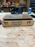
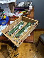
For comparability's sake I use a resistor as load. For a functional test the reactive load makes a lot of sense. For that I use a cheap 4" driver with huge parts of the cone removed. The remaining paper is stiffened up with epoxy. There still is sound, but way less then with an intact speaker.In the workbench real testing, better use a speaker while wearing earplugs.
Why is the lower the output Z the less subjected to 'reactance' which is not what I said.
First the output Z needs to be more than 0 otherwise destruction, second, I am talking about the path to ground in the open loop when subjected to signals and capacitor which grounds certain frequencies, at these the GNF becomes is reduced and gain raise!
First the output Z needs to be more than 0 otherwise destruction, second, I am talking about the path to ground in the open loop when subjected to signals and capacitor which grounds certain frequencies, at these the GNF becomes is reduced and gain raise!
YMMV, but I think a high damping factor is typically most relevant below around 200Hz, where box tuning is used to augment and tune the bass.Something I haven't seen discussed so far is the effect of DAMPING FACTOR on sound quality and how it affects the quality of sound with different types of loads.
At higher frequencies, I think current-drive opens up possiblities for outright better THD results for many speakers, as well as lower IMD and other distortions from magnetic hysteresis: less "crackle and pops" and so on. etc). At minimum, any speaker that is connected will probably need some custom EQ to adjust the tonal balance. So the project may as well be treated as an active speaker, no matter the aethetics of what the build physically looks like. But I think it's worth it, especially with full range drivers, where the stakes are so much higher because of the wide frequency range.
My favourite feedback style is mixed-mode. In one form, the '1k ohm' of a 30k:1k divider for the usual voltage feedback is lifted from ground and connected to a 0.1~0.5 ohm shunt resistor, with a small capacitor for AC coupling. So the main source of feedback varies, depending on frequency.
One idea that comes to mind is you could have an adjustment knob that alters the damping factor (within limits, depending on stability). I was thinking about trying out a TQWT cabinet build, and it would be a great alternative to using a mechanical window to add or remove stuffing from the speaker boxes!

Yes, damping does affect the bass... for sure.. but there's likely the most THD in there in the interface between amp and speaker... where maximum mechanical movement is required ( again, all distortion needs to be examined in the frequency spectrum! ).
Example, I got an ICE amp that has very low output impedance... you ought to hear its control over the bass. Sure, it sounds veiled in the upper frequencies, but that another story...
The idea behind a knob that alters the amp characteristics is very interesting. I think the SIT1 introduced some idea of that, but there are other aspects of the system that might have more impact... I do believe that the amp/speaker interface is the most important part of the entire chain....
I think we can address things like noise, reasonable distortion, etc... but the level of power involved in driving the speaker is orders of magnitude greater and is in there that we have the greatest impact -and opportunity- on generating a facsimile of the recording
Speaking of getting loaded!For comparability's sake I use a resistor as load. For a functional test the reactive load makes a lot of sense. For that I use a cheap 4" driver with huge parts of the cone removed. The remaining paper is stiffened up with epoxy. There still is sound, but way less then with an intact speaker.
Attachments
Damping factor is just an indication of the ability to send current in a low resistance. It means nothing in terms of quality of the damping. The power supply noise becomes much more important at this point.
If I unplug the power to my power amp it plays without breaking a sweat for 10 seconds at loud volumes, then the regulators cant sustain and it shuts off. If I plug it back it restores full power in less than half a second.
Same with my power tube amp, I cannot hear the difference much at 50% of main power, the sound is still quite clear and dynamic. The inner quality remains.
A "class A" probably is influenced a lot by the mains because it uses a lot more idle power and if you unplug it it probably stops in 1-2 seconds with major sound degradation.
Damping factor is not the ability to deliver a current, foremost it is the ability of the amp to negate a perturbation
that is present at the output but not at the input, FI a unity gain 5532 has very low output impedance by the virtue
of a gigantic NFB and despite a very low current capability, and can have a higher DF than a low NFB power amp.
Reactive power supplied by the load is the most common perturbation, wich mean that a high DF will keep the amp s
distorsion constant even with a reactive load while a low DF amp will see the distorsion increasing even if it has
the same current capablity.
Hi all,
it is natural that on a amplifier forum damping factor is seen only as amplifier issue and amplifier distortion issue, right, but it has huge effect on the loudspeaker transducer distortion performance. Two amplifiers with different putput impedance but with similar distortion measured in electric domain might result different distortion measured in acoustic domain.
If one connects a transducer to an amplifier with just a cable, the amplifier output impedance is in series with the transducer. Now as the transducer cone moves as you start listen to music the transducer generates voltage (back EMF) which causes some current over the impedance in series with it. The amplifier is load for the driver! The current a transducer generates of course flows through voice coil at the same moment and causes force in the motor thus there is acoustic output! The lower the load impedance the more the current, right, in this case the amplifier is load for the driver.
So, a transducer is another voltage source in the circuit, it's not just the amplifier and depending on series impedance it would affect acoustic output. Because any and all current in the circuit means force in the motor and acoustic output, the driver has ability to make sound on it's own! Or change the sound, depends on how you want to think about it.
Around the driver main resonance this is electrical damping, because moving mass is cancelled by spring and all the force in motor turns directly into velocity so opposing current happens as per Lenz law. Hence the name "damping factor", the driver dampens itself! Amplifier has nothing to do with this other than provide low impedance path for driver to dampen itself electrically. Low amplifier output impedance allows transducer to make it's own movement opposing current that opposes the movement. Above main resonance there is no damping as current generated has phase shift to it due to accelerating mass, thus it's only driver emitting it's own non-linearities into acoustic domain.
Usually forum talk is that amplifier is controlling the driver, but in fact voltage amplifier never controls a driver, the driver is controlling itself and only at the main resonance assuming series impedance is low. Only current amplifier, so high output impedance (low damping factor) amplifier would control a driver, because it is in charge of the current in the circuit. Also, if series impedance of driver was high so that the driver cannot generate/affect much current in the circuit. See? This is about biggest myth that's been floating around for ages and continues to do so. Please read Esa Meriläinen book about current drive.
Personally, my opinion is people can talk about amplifier controlling driver with it's low damping factor because most of the time it's kinda what happens, driver is being controlled due to high damping factor just not by the amplifier so it's semantics. It's kinda hard subject to grasp, understanding how a transducer works simultaneously as a motor and generator is not exactly intuitive. But, sometimes this "backwards thinking" attributing this stuff to amplifier and not understanding it's about the transducer could prevent one actually making a good system, taking advantage of the phenomenon to really make low acoustic distortion system. I mean, the amplifier alone is not audible audio yet, only after conversion to acoustic sound it becomes audible and the conversion is done by a transducer so it's very important to understand the whole system and process. One would likely want low series impedance for drive resonance to dampen itself and high series impedance above to reduce distortion emitting to acoustic domain. This could be done manipulating amplifier output impedance, but it's typically dominated by impedance network between amp and transducer, a passive crossover.
ps. I do not know how significant amplifier distortion is in this regard, it might be, but unless a driver motor is very advanced distortion in acoustic output is likely dominated by driver motor distortion, which can be reduced by utilizing impedance in series with it.
Last edited:
I did a quick simulation af my amplifier.
Connected a sine source as load: 1 kHz, Ri 8 ohms, 1V. Parallel resistor 1k. Input shorted.
Result: 0.0008V across the 1k resistor.
Now it could be interesting to see what amount of that signal possibly travels back to the input. Remove the short and put 100 ohms there.
Connected a sine source as load: 1 kHz, Ri 8 ohms, 1V. Parallel resistor 1k. Input shorted.
Result: 0.0008V across the 1k resistor.
Now it could be interesting to see what amount of that signal possibly travels back to the input. Remove the short and put 100 ohms there.
Hi BernHard long time no see, how are you doing!? = that is an extreme test your doing 🙂
(tmuiku), you said: Only current amplifier, so high output impedance (low damping factor) amplifier would control a driver, because it is in charge of the current in the circuit. Also, if series impedance of driver was high so that the driver cannot generate/affect much current in the circuit. See? This is about biggest myth that's been floating around for ages and continues to do so. Please read Esa Meriläinen book about current drive.
I am confused: current amplifier = high damping factor low output Z which is a typical transistor output stage, darlington etc.
I could not measure any increase/decrease at the loudspeakers measurements in THD from a current output low Z and a low power tube voltage/transformer drive with Z out of 1.5.
It will affect the impulse and damping of the drivers but the THD is the same as well as frequency response!
No difference with Z=0.1 or Z=1.5 and current / transformer drive. ZERO measurable difference.
Hi, the driver re and cable is in series with the backEMF, so say with nominal 8ohm driver circuit impedance is already about 8ohms, additional 1.5ohms doesn't mean much. If your output impedance was also 8ohms you'd slash driver motor distortion in half, because load for backEMF was doubled. You could do temporary tests with a resistor in series, say 8ohms or 16ohms, or what ever you have in hand.
Ideal current amp would have infinite output impedance = driver cannot affect circuit current = it's own acoustic output. Ideal voltage amp has 0 output impedance = driver has maximal effect on current in the circuit so pretty much dominates it's own acoustic output.
Yeah frequency response, so impulse and damping, would change of course with the added series impedance, because the driver doesn't do the current anymore but the amp must! Now you'd just EQ before the amp, or with impedance network between amp and the driver.
~all drivers are desiged to give ~flat response with voltage drive, a condition where the driver determines current so it basically EQs itself 😉 When you take away this ability by dominating circuit current with some other bigger impedance (than the driver) you take a way driver ability to control current in the circuit. Any current through voice coil turns into acoustic output so now your amplifier is responsible, or in control, of acoustic output, not the driver.
If you think it through you'd likely want low output impedance amplifier to allow nice electrical damping where needed, AND impedance network between amp and driver to increase impedance where benefitical. My post was mainly to give perspective on the subject that acoustic output is not controlled by high damping factor (low output impedance) amplifier but the transducer itself, or impedance network in between 😉 Magic is mainly with the speaker design.
Last edited:
Yes! , I just finished diy tall bookshelf speakers and they sound not so good with my SS amp, I will test again with my tube amp, maybe something I am missing which is not measurable.
This, I think, is a great approach. Especially since the alternative with amplifier R&D is out of reach for most people.If you think it through you'd likely want low output impedance amplifier to allow nice electrical damping where needed, AND impedance network between amp and driver to increase impedance where benefitical.
With reasonable headphones, I can sometimes hear the nuances of speaker tests when people post them on YT, despite the obvious limitations.
I've been looking at ideas for my next project:
Fostex FE126NV2 single driver,
Maybe the FE166NV2 or even the 8", but my only experience with whizzers were ancient TV speakers of questionable quality. Nonetheless, I'm curious and wonder if the whizzer also helps stabilise the voice coil against unwanted vibrational modes (like coin spinning effects). There was a video with a back-to-back comparison of the 6" FE series vs the FW series, and for some reason I didn't like the latter, even though it was meant to be the higher-end driver. Another possible difference might be the cloth vs rubber surround.
The effect of different box types was illuminating.
Some of the back-loaded horns had a sort-of catacomb effect on vocals. However, there were a couple of great ones, and I wonder what they did differently. Maybe some additional S-bends to filter out the treble? Or just a better horn profile?
On YT spcjpnorg 2 ( @nandappe ?) makes some amazing-sounding recordings with QW boxes. Other driver ideas include pretty much half of the Markaudio range from 9cm diameter and up.
Hi, the driver re and cable is in series with the backEMF, so say with nominal 8ohm driver circuit impedance is already about 8ohms, additional 1.5ohms doesn't mean much. If your output impedance was also 8ohms you'd slash driver motor distortion in half, because load for backEMF was doubled. You could do temporary tests with a resistor in series, say 8ohms or 16ohms, or what ever you have in hand.
Ideal current amp would have infinite output impedance = driver cannot affect circuit current = it's own acoustic output. Ideal voltage amp has 0 output impedance = driver has maximal effect on current in the circuit so pretty much dominates it's own acoustic output.
Yeah frequency response, so impulse and damping, would change of course with the added series impedance, because the driver doesn't do the current anymore but the amp must! Now you'd just EQ before the amp, or with impedance network between amp and the driver.
~all drivers are desiged to give ~flat response with voltage drive, a condition where the driver determines current so it basically EQs itself 😉 When you take away this ability by dominating circuit current with some other bigger impedance (than the driver) you take a way driver ability to control current in the circuit. Any current through voice coil turns into acoustic output so now your amplifier is responsible, or in control, of acoustic output, not the driver.
If you think it through you'd likely want low output impedance amplifier to allow nice electrical damping where needed, AND impedance network between amp and driver to increase impedance where benefitical. My post was mainly to give perspective on the subject that acoustic output is not controlled by high damping factor (low output impedance) amplifier but the transducer itself, or impedance network in between 😉 Magic is mainly with the speaker design.
Neat reading... thanks
(1) So, speakers are to be thought of as a transformer of sorts? If you apply a voltage across them the you will generate movement but there is some mass that is accelerated, decelerated and so that creates a mechanical resistance... a hysteresis of sorts. that creates the back EMF. And current.
(1a) The back EMF is a function of mass. So, all things being equal, a woofer will provide more back EMF and a tweeter less back EMF. Also, different kinds of speaker designs will generate different types of back EMF... planars, dynamic, ribbons, etc... ( interesting -purely as an aside comment-, not plasmas ).
(2) If you drive a voltage amplifier, then mechanical resistance from the driver's mass resisting the movement will be allowed to generate a current that modifies the voltage. If this current is completed in a circuit at the amplifier, so if the amplifier has low return impedance, the speaker will be able to create the current, sink it into the amp and the sound will be modified by the speaker assembly. Think the case where the return connection to the speaker is at a ground level -at ground.
(3) If you drive a current amplifier, then the mechanical resistance of the speaker will attempt to generate a back current but it will see a high impedance, so the speaker will be FORCED to follow the signal coming from the amplifier. There is no way to dump that current. What will then happen to the back EMF? I think it will generate HEAT? So the speaker might... ahem... burn up?
(4) Smaller drivers can sink less heat, while larger drivers, with more massive structures can disspate the heat. So, would that mean that a woofer is safer with the current drive amp? While the tweeter might want a voltage amp ( although there is less power being driven through the upper frequencies - more on that anon. ).
(5) So, do different types of the frequency spectrum require a different type of amplifier to protect the speakers? Can we address this via the crossover circuit by adding some resistance in it? So the tweeter might see a high output impedance current amplifier and the woofer a low output impedance voltage amplifier? Or even, gulp! viceversa?
(6) How about planar speaker designs that are mostly resistive and the back EMF effect is much smaller given the far lighter ( less mass ) membranes they use to generated the acoustic wave?
(6) Hmm... then you got bridged amplifiers.... where neither side is at ground level. By definition we say that their damping factor is halved. Hmm... Yet, they would seem to have to have a higher output impedance, eh? Neither leg of the speaker output circuit is at ground level then since we normally are looking at the difference between the Plus legs of each circuit driven out of phase.
I find this discussion fascinating, btw. The idea that damping does not affect the distortion in general is nonsensical -IMHO. Things like impulse behavior, where the rise and fall times are affected and oscillations like ringing, overshoot, undershoot, are all distortion creating events that affect the time and frequency domains of the acoustic waveform generated by the speaker.
I got the feeling that the amp - speaker interface is the source of most of the distortion.
Last edited:
In the open loop case, the EMF will be a voltage. Typically, a "current amplifier" should still operate on the same basis as a voltage amplifier with voltage feedback, it's just that the location of the feedback has changed to voltage across a current-sensing resistor, usually on the grounded sided of the speaker.(3) If you drive a current amplifier, then the mechanical resistance of the speaker will attempt to generate a back current but it will see a high impedance, so the speaker will be FORCED to follow the signal coming from the amplifier. There is no way to dump that current. What will then happen to the back EMF? I think it will generate HEAT? So the speaker might... ahem... burn up?
With what you're describing, there's just no current, so there's no power dissipated and no heat. But that's not say that current-drive can't be misused. In extreme cases, where thermal compression starts, a voltage amplifier naturally provides less power, but a current amplifier could burn out the speaker quickly.
With what you're describing, there's just no current, so there's no power dissipated and no heat.
Hmm. Think of hysteresis. The speaker has mass so it can not follow the signal exactly, it will always be behind it, it will overshoot, it will undershoot, vibrations, etc.
That creates a movement in the magnetic field of the coil which is different from the current ( or voltage, but we'll leave that for a different discussion ) that is being applied across the coil.
That is an energy. Where does it go? If you have a very high amplifier output impedance then that energy can not generate a current. So the only place I can think it can go is heat.
The price you'd pay for driver accuracy would be heat.
Z can be observed on impulse behaviour , it will savour the sound but it is negligible in the thd and frequency readings
The problem is that the impedance reactance resistance is not constant with the frequency and is non linear and some components of it asymmetrical , that poses a serious challenge for the music signal because it will modulate the whole amplifier demand of voltage and current which will cause noise and loss of dynamics and power.
I don’t think the emf component is so bad , this can be easily measured by placing two loudspeakers face to face and feed the output signal to amplifier output then use a 3rd loudspeaker in another room which is // connected the the amp output
So Tony , I don’t know if I get it right , amplifier Z out is the impedance and the lower the higher the damping factor , so a low damping factor means it is loss in heat, I thought the opposite that the lower (not the higher) Z out then a path for emf to dissipate and not generate voltage , dissipate in heat ,, as in high Z the voltage is created and send to amp input through feedback and resonates
I think the membrane will move exactly where the amp tell it.
And then it will have vibrations dissipating on the membrane , flexions then perimeter stationary waves and many break up patterns , but it general it will easily follow a sine wave and many more in a linear fashion
And then it will have vibrations dissipating on the membrane , flexions then perimeter stationary waves and many break up patterns , but it general it will easily follow a sine wave and many more in a linear fashion
- Home
- Amplifiers
- Solid State
- Does THD accurately predict good sound quality? And is subjective SQ useful to assess amps?