No, it's all about the goal in #47, to proove I'm right with these 'vfet'-compounds (it also works with bjt's and mos).
The matching for the amp was quick & dirty with the betatester in the meter.
For the Sziklai's I matched the low beta npn's with high beta PNP's and vice versa to get near equal base currents. Within 20%, which is sufficient.
The matching for the amp was quick & dirty with the betatester in the meter.
For the Sziklai's I matched the low beta npn's with high beta PNP's and vice versa to get near equal base currents. Within 20%, which is sufficient.
My friend´s SOA detection limiter was roughly based on that, he did not try for microseconds but about a millisecond which he thought was "safe" ... sadly not enough 🙁RCA had an app note (in the early years) for a non-destructive second breakdown tester. It worked by detecting a rapid drop in Vbe at the onset of second breakdown. But it has a LOT of emitter degeneration and operated within microseconds.
In an audio amp, you can’t have 12 to 15 volts of drop in the emitter resistors. Nor can you make a VI limiter activate in microseconds. When you make one that DOES act that fast, it almost always results in severe instability and oscillation when activated. You always end up intentionally slowing it down for stability, so the local feedback of the limiter isn’t fighting the global feedback of the amp in a vicious circle. It won’t be fast enough to prevent damage from second breakdown when it is actually occurring - you need to limit at a lower current and not wait for it to happen and try to stop it.
I built a breakdown tester straight from the RCA book, it was electromechanical (remember, late 60´s book), a small motor turned a pinky sized bar magnet near a reed relay (the lowest mass fast relay type available) chopping Base current; transistor was choke loaded, and inductive kick pulse swept voltage and current on its own, no need for fancy waveform generators.
You could clearly see the breakdown point on a scope screen, you could also see second breakdown which was non destructive if you were careful with energy stored in inductor.
A crude "power" curve tracer if you wish, it was useful, but after some time it became redundant, way back then "good family" components (RCA, Motorola, Siemens) parts could be trusted, no need to measure each new batch.
It would be interesting to build one today (mine disappeared after moving many times) to test "mystery suppliers" products.
Last edited:
Reactive load can change things.
In a generalized manner impedance and impedance phase.
It is almost comical to do AC analysis
of a resistor in spice.
Just to be assured
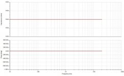
it behaves as expected. 8 ohm resistor gives you a
boring straight impedance of 8 ohms.
And a boring straight impedance phase as well.

Can make a very basic reactive load
So we can get a 1ohm hit below resonance
which is more inductive.
And a 1 ohm hit above resonance
which is more capacitive.
With a more realistic impedance phase flip.
Aka very generic
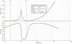
speaker model with Re of around 1 ohm
Fs around 100 Hz

Ac analysis showing impedance and impedance phase.
I marked point A and B
22 Hz for a 1 ohm hit more inductive
200 Hz for 1 ohm hit more capacitive.
hits will be more realistic reverse phase.

images should be large in attachment
In a generalized manner impedance and impedance phase.
It is almost comical to do AC analysis
of a resistor in spice.
Just to be assured
it behaves as expected. 8 ohm resistor gives you a
boring straight impedance of 8 ohms.
And a boring straight impedance phase as well.

Can make a very basic reactive load
So we can get a 1ohm hit below resonance
which is more inductive.
And a 1 ohm hit above resonance
which is more capacitive.
With a more realistic impedance phase flip.
Aka very generic
speaker model with Re of around 1 ohm
Fs around 100 Hz
Ac analysis showing impedance and impedance phase.
I marked point A and B
22 Hz for a 1 ohm hit more inductive
200 Hz for 1 ohm hit more capacitive.
hits will be more realistic reverse phase.

images should be large in attachment
Last edited:
That is far more reactive than most speakers are. If a speaker really had that much reactance compared to resistance across most of the band there would be very little output. In real speakers, there is a decent amount of power transfer to cone motion in the midband, and a good portion of the band staying within 30 degrees. 60+ degree excursions are not abnormal - just not everywhere
Great model of an LS! Digging up design and doing ac analysises soon.
Do you have a model of a planar (eg Final 0.4) too?
Do you have a model of a planar (eg Final 0.4) too?