It appears to me that the one bridge side is actively responding to the clipping and activated limiter of the other (and vv). Current is swung up and down the load, and audiable....
The path that I am interested in is: what happens if, for whatever reason, the protection is activated? Can the audible impacts be minimized? Is this not a noble pursuit?
...

Yes, I have seen this discussed in another thread where they are seeking a design that does not produce distortion until you are very close to clip limiting.If you want to minimize the audible effect of VI limiters activating you need to add another feature also used on most PA amplifiers - clip limiting.
A simple solution to the misbehavior that I described is to forgo the V-I limiting altogether and use simple fixed current limiting in both amplifiers to prevent catastrophic failure in the event of a short between output terminals or either terminal to ground. The problem with this is that you must sacrifice a lot of output power or add many output pairs. Even with todays most robust BJTs, the allowable short circuit current with, say 65V rails, is fairly small. Bridge mode actually is a benefit with this approach as you can lower the supply voltage to approximately 1/2 and still maintain the output power of the unbridged amplifier. The allowable current per transistor pair is then doubled.
You have been holding out on me! 🙂 I would be most interested to see them. I will also take a closer look at #22.It can be done, but there is a more straightforward solution. A 'interwoven' (opamp-style double inverter amplifier with pos and neg output) bridge amplifier is a good solution. I'll try to find my design of it in my archives.
Only the negative side limiters with the lower thresholds activate. The two positive side limiters having higher thresholds never activate. The two negative side limiters take turns activating on alternate half cycles of the waveform. At no time is more than one limiter active.It appears to me that the one bridge side is actively responding to the clipping and activated limiter of the other (and vv). Current is swung up and down the load, and audiable.
Can be unbalance of components and tolerances. NPN's and PNP's differ substantial, and their beta's. The one may trigger already where the other remains indifferent.
Yes. Although the Spice models for the pre-drivers and drivers have matched NPN-to-PNP beta's, the output transistor betas (NPN & PNP) are quite different.Can be unbalance of components and tolerances. NPN's and PNP's differ substantial, and their beta's. The one may trigger already where the other remains indifferent.
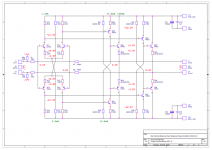
Symmetrical differential front stage, and a double Sziklai output: the Hiraga Bridge.
Named after Jean Hiraga, to honour the master.
This is my 'small exercise' design, somesort proof of concept of an 'interwoven' balanced bridge design.
Open loop bandwith (in simulation) close to 100kHz.
No rocket technology involved.
Bonus: no balanced input signal needed.
Extra bonus: no popping, no safeties needed.
Goal is to omit Q23, Q24, Q33 Q34 and replace Q21, Q22, Q31, Q32 with low output impedance ('v-fetish') compounds on which I'm working now (very promising).
Attachments
It WILL clip like VI limiter does: ugly.The path that I am interested in is: what happens if, for whatever reason, the protection is activated?
There is no escape from that.
No, it IS a VI limiter, VERY obnoxious when triggered.Can the audible impacts be minimized? Is this not a noble pursuit?
Sadly, many noble pursuits have no solution.
Again, NO.Now, to expand on my first post and its attachment. If you have a conventional amplifier with a single-ended output driving a pure resistive load to ground, it is possible to design a V-I limiter that clips the waveform fairly cleanly (flat tops and bottoms).
A VI limiter, by definition, once triggered LOWERS current trough device, it does not keep it steady.
So NO FLAT TOP.
You really need to see VI limiter waveforms to understand it.
Only pure current limiters yield flat tops, and that into resistive loads.
Reactive loads? ... inject a perfect squarewave into a reactive load and look at current waveforms yourself.
Alternatively, inject a current squarewave and look at voltage waveforms developed.
You won´t "get" it until you see his, apparently, and no, Physics is not a matter of "opinion".
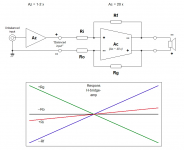
As show thousands of times, a proper usable VI limiter CAN be made, it simply needs to be properly DESIGNED.There may be some overshoot and undershoot, but this can be mitigated by the proper protection loop frequency compensation. Now, if instead of grounding one end of the load resistor, we connect it to the output of another amplifier driven out of phase, then the V-I limiter reacts to the second amplifier pulling on the resistor even after it has started to limit. This behavior was described in detail in the attachment to #1. It produces a very different waveform from the case where the resistor is grounded. Those "bat wings" that I described have much greater high frequency content and are much more audible. I have built this and heard this in my listening room (40 yrs ago - I'm old 🙂). As rayma said back in post #4, some form of master/slave protection for the bridged mode is required to make the two cases perform similarly. This is what I seek. I understand that this does not address reactive loads or other issues but it is, to me, an interesting design challenge that has some merit. You are free to disagree.
Bruce
Your short path of taking an already designed one (for a single amplifier that is) and plain bridging it without further consideration, will most probably fail.
You´ll need to learn and design a proper one for bridged amps by yourself.
Or maybe some caritative soul designs one for you. 🙂
Or copy some properly designed one, such as those from Peavey (or any other competent Manufacturer)
I suggest you download and study Commercial PA amps, most except QSC (whch in general use plain current limiting) or those brave souls relying just on fast Mains breakers (BGW) 😱
Asians in general trust their own dedicated DC and short protection ICs, but those are NOT VI limiters either, they trigger a relay to open load away within 5 seconds.
EDIT:
NOW we´re talking 😉A simple solution to the misbehavior that I described is to forgo the V-I limiting altogether and use simple fixed current limiting
I'm not sure why it always seems to me that you think I am disagreeing with you. I haven't yet.It WILL clip like VI limiter does: ugly.
There is no escape from that.
I agree, if VI is implemented in a bridged amplifier, it will be ugly. In my last response to you, I explained that in a bridged amplifier it is much uglier than in a non-bridged amplifier. I did not want the additional ugliness 🙂.
Again, the goal was to make it no worse that the non-bridged amp.No, it IS a VI limiter, VERY obnoxious when triggered.
Sadly, many noble pursuits have no solution.
Nobility may be in the eye of the beholder. 🙂
Now, this is the first time that I must respectively disagree with you. The VI limiter lowers the current limit threshold in response to an increase in the voltage across the output transistor. In a normal amplifier, the only forcing function for increasing Vbe is the feedback loop for the amplifier which keeps trying to raise the output level as the limiter drains away the drive current. If the limiter control loop is stable, an equilibrium will be reached between the two loops and the waveform will flatten. Now, will it be perfect in real life? No. There can be interaction with reactive loads (though I was trying to exclude them for this exercise) and power supply ripple feedthrough. In a bridged amplifier, there is a second forcing function, which is the other amplifier pulling on the load. This upsets that equilibrium and makes it even more ugly.Again, NO.
A VI limiter, by definition, once triggered LOWERS current trough device, it does not keep it steady.
So NO FLAT TOP.
What makes you think that I have not seen the waveforms? I have designed, built, and tested 3 PAs with VI limiting and they all exhibited relatively flat tops, albeit with initial overshoot, when driving resistive test loads. It also shows that way in simulations. The simulation I used to generate the attachment in #1 uses the LTSpice model for a real working amplifier. The only shortcut taken with the simulation was to use Spice's ideal voltage sources for the power supplies. I have both simulations and digital scope plots from the latest amp. I will find and post. I have been designing, building, measuring, and listening to amplifiers since high school. The earliest were tube amps (no VI limiting 🙂).You really need to see VI limiter waveforms to understand it.
I agree that they do make a cleaner wave form but you can get close with VI if you work at it.Only pure current limiters yield flat tops, and that into resistive loads.
I don't disagree with you on reactive loads. The waveforms are ugly!Reactive loads? ... inject a perfect squarewave into a reactive load and look at current waveforms yourself.
Alternatively, inject a current squarewave and look at voltage waveforms developed.
You won´t "get" it until you see his, apparently, and no, Physics is not a matter of "opinion".
You misunderstand me. I know there is no short path. If there was, I wouldn't have asked the question. I just used that for ease of description/argument.Your short path of taking an already designed one (for a single amplifier that is) and plain bridging it without further consideration, will most probably fail.
So, am I to assume that you are not a fan of V-I limiting. 🙂EDIT:
NOW we´re talking 😉
Thanks for all of your input!
I doubt this seriously. Two loops of a completely different kind in harmony? The feedback loop keeps driving the amp to its desired setpoint no matter what, the limiter undermines it until release. The strongest win, bending or bursting....If the limiter control loop is stable, an equilibrium will be reached between the two loops and the waveform will flatten...
Now if the limiter also changes the feedback loop, a to be determined setpoint will be reached. When in bridge mode, any present limiter (there are four) kicking in should influence both feedback loops. I could maybe concieve such a circuit (to answer your initial question), but I'm not tempted (and involved into another design). And it must be fast, which is a serious challenge with feedback loops.
In a classic bridged amplifier, there are two controlling feedback loops 'unaware' of 'the other'. Once confronted to each other by a (one, not two needed) acting limiter, both feedback loops will respond corresponding, but in their own 'interest' only. That's where all the additional circuitry is needed for in pro gear....In a bridged amplifier, there is a second forcing function, which is the other amplifier pulling on the load...
But you can´t ignore reactive loads, which is what you´ll hear through.
Anything else is just an "interesting exercise" but doesn´t solve your original problem: ugly sound.
And for the nth time: avoid the problem altogether, design a proper VI limiter to begin with.
Or, if too complex, do not use them.
Anything else is just an "interesting exercise" but doesn´t solve your original problem: ugly sound.
And for the nth time: avoid the problem altogether, design a proper VI limiter to begin with.
Or, if too complex, do not use them.
What is your preferred approach to amplifier protection?Just read my earlier posts:I am not 🙂
- Home
- Amplifiers
- Solid State
- Do You Have a Solution for Bad Behavior of V-I Limiters in Bridged Amplifiers?