As soon as one of the amps (non-inv / inv) enters its limitations, the negative feedback wil try to 'correct' that. That's not really wanted, but the other amplifier (inv / non-inv) 'notices' odd behaviour by the load (the speaker and the other amp), and tries to 'correct' too. Two amp's will fight each other unless some 'coupling' is made, being balanced or as 'master-slave'.
Splitting this case (both the amps and the pondering about) into two separate identities, as if it were two near perfect amps, avoids the more complex bridged configuration. Signal processing is one thing, stability (in extreme performance) is another.
Forget the signal and apply a large dc voltage to an input up just over where the V-I limter (-s) kick in. What is the dc situation then? Is it stable, does it still works as intended? Does it release it's 'gripping' once the extreme exitation disappears?
What is needed? A very different approach, concept, topology and solution I'm afraid. There are too many variables and to few equations here. To address all the variables, more control (-loops) is (are) needed anyhow.
Define "optimally designed"To word it differently: Given two amplifiers, each with optimally designed V-I limiters, is it possible to operate the amplifiers in bridge mode without incurring additional audio degradation?
IF each one had an optimally designed VI limiter for SINGLE/independent use, it will NOT be optimally designed any more when bridged, which quadruples power output.
You´ll need a custom design, considering the doubled current output.
One answer has already been suggested above: DOUBLE the output stage at EACH amp.
As of "improving sound", a "nice clipping" VI limiter is an oxymoron, it will NEVER sound "nice" and it´s in its nature; it will always give you some kind of foldback response, lowering (usually halving) output current from its peak value; the resultant funky waveform sounds UGLY, specially if into a reactive load (hint: speaker).
FWIW practically ALL commercial PA amplifiers, typically in rack mounts but also in, say, powered mixers, BOTH have VI limiters AND are bridgeable 😱
They are used that way all the time without complaints ....
EDIT: this is the famous indestructible Peavey CS800, the 1994 version.
It DOES have classic VI limiters and it is DESIGNED to be used bridged.
As you see, both characteristics are not incompatible.
Attachments
Last edited:

Yes! I has hoping someone had worked this.A very different approach, concept, topology and solution I'm afraid.
An optimally designed limiter closely follows the transistors' SOA specification and does not violate it under and any circumstances. This includes designing it for transient and steady state conditions as the SOA is different for different durations. You cannot do any better than this in bridged if you are just considering transistor protection.Define "optimally designed"
#22, commercial available. Not DIY.Yes! I has hoping someone had worked this.
But these are only just a few of all the involved variables. One has to include and manage all specs, individual and overall.An optimally designed limiter closely follows the transistors' SOA specification and does not violate it under and any circumstances. This includes designing it for transient and steady state conditions as the SOA is different for different durations. You cannot do any better than this in bridged if you are just considering transistor protection.
Yes, this is necessary for maximum output power, but again, this is an attempt to avoid activation of the SOA protection. This is a good thing, and the right thing to do. I don't disagree, but I am, however, searching for an improved limiter. Even with an improved limiter, one should take every measure to avoid activating it. Sorry if I have not made myself clear that this is more of an academic, rather than practical exercise.One answer has already been suggested above: DOUBLE the output stage at EACH amp.
For the overall system, I agree but my simplistic definition of "optimal" extracts the maximum output current from the output transistors while keeping them fully protected. If you need more current, you need more transistors.But these are only just a few of all the involved variables. One has to include and manage all specs, individual and overall.
Now you fold back to #22 & #19 on this specific design consideration.For the overall system, I agree but my simplistic definition of "optimal" extracts the maximum output current from the output transistors while keeping them fully protected. If you need more current, you need more transistors.
Imagine the golden gate bridge: each column is capable to carry the weight of the whole bridge, but not to tear the other down.
What considerations had passed and were reviewed during the design, then? All and everything was issued.
Yes, this is necessary for maximum output power, but again, this is an attempt to avoid activation of the SOA protection.
You think them independent from each other?
They are not.
They are two faces of the same coin, two ways to say the same thing.
Until you "get" that, your quest has no answer.
Then you are not looking for a VI limiter but some other kind.This is a good thing, and the right thing to do. I don't disagree, but I am, however, searching for an improved limiter. Even with an improved limiter, one should take every measure to avoid activating it. Sorry if I have not made myself clear that this is more of an academic, rather than practical exercise.
I think we've said what needs to be said. If you bridge two amps then the voltage and current output double, so that's 4x power. The VI limiters will think you've changed your load to a quarter and will trip. A bridged amp circuit needs to be designed to handle the current and power.
Ths simplest approach would be to double up the number of transistors - both amps - and then you MAY be able to change the IV limiters to handle the increased power. Then you may need more drive current and so on. So it's not a particularly easy nor quick way to get loads more power "for free".
Ths simplest approach would be to double up the number of transistors - both amps - and then you MAY be able to change the IV limiters to handle the increased power. Then you may need more drive current and so on. So it's not a particularly easy nor quick way to get loads more power "for free".
Ooops! - halved, not quarter load. But I was thinking at the time that the IV limiters should be able to allow quarter of the original load so as not to trip during normal operation.
Parallelling the transistors would allow double the current and you may even be able to use the existing IV limters, but the driver current capability needs to be able to handle the increased loading too.
Parallelling the transistors would allow double the current and you may even be able to use the existing IV limters, but the driver current capability needs to be able to handle the increased loading too.
So, the optimally designed V-I limiters should be improved and not to be activated in an application it was not intended for....Even with an improved limiter, one should take every measure to avoid activating it...
Ehmm... I'm trying to bridge this.
😉
Citizen124032, I saw from your first post (#2) that you seem to understand what I am trying to do and the various issues involved, but I must say that this statement has me baffled. Could you decode it for me, please?Imagine the golden gate bridge: each column is capable to carry the weight of the whole bridge, but not to tear the other down.
What considerations had passed and were reviewed during the design, then? All and everything was issued.
If you want to minimize the audible effect of VI limiters activating you need to add another feature also used on most PA amplifiers - clip limiting. Most of these amps have a circuit that detects instantaneous loss of feedback and uses that signal to dial the gain back. Sure it’s “audible” - but less objectionable than sustained clipping. VI limiters also cause a loss of feedback, so as far as the compressor is concerned it’s indistinguishable from clipping. The reduced level may not activate the VI limiter on the next pulse, unless it’s caused by a shorted speaker wire or something equally bad. After the transient passes, the gain returns to normal after its time constant has discharged. The gain reduction is not drastic, and tends to track with the amount of overdrive. If you can hear it “pumping” the system is being driven way too hard.
If you are constantly hitting the VI limiters you need more amplifiers. A novice PA operator might connect two more speaker pairs in order to get more “punch”, just to hit the VI limits, activate the compressors, and get no more output than one pair of speakers did. The red lights will sit there flashing the whole time, even without any blatantly obvious distortion. When this is ignored, it will overheat.
If you are constantly hitting the VI limiters you need more amplifiers. A novice PA operator might connect two more speaker pairs in order to get more “punch”, just to hit the VI limits, activate the compressors, and get no more output than one pair of speakers did. The red lights will sit there flashing the whole time, even without any blatantly obvious distortion. When this is ignored, it will overheat.
JMFahey,Until you "get" that, your quest has no answer.
What I "get" is that you and I are on separate paths and I have, as yet, been unable to convince you that mine has any merit. I may now understand where I went wrong from the first post on. Please let me try again.
You and others in this thread are on the path of avoiding activation of the protection circuitry. If it is never activated, then its audible effects are irrelevant. No argument. This is valid - case closed; we are done.
The path that I am interested in is: what happens if, for whatever reason, the protection is activated? Can the audible impacts be minimized? Is this not a noble pursuit?
Now, to expand on my first post and its attachment. If you have a conventional amplifier with a single-ended output driving a pure resistive load to ground, it is possible to design a V-I limiter that clips the waveform fairly cleanly (flat tops and bottoms). There may be some overshoot and undershoot, but this can be mitigated by the proper protection loop frequency compensation. Now, if instead of grounding one end of the load resistor, we connect it to the output of another amplifier driven out of phase, then the V-I limiter reacts to the second amplifier pulling on the resistor even after it has started to limit. This behavior was described in detail in the attachment to #1. It produces a very different waveform from the case where the resistor is grounded. Those "bat wings" that I described have much greater high frequency content and are much more audible. I have built this and heard this in my listening room (40 yrs ago - I'm old 🙂). As rayma said back in post #4, some form of master/slave protection for the bridged mode is required to make the two cases perform similarly. This is what I seek. I understand that this does not address reactive loads or other issues but it is, to me, an interesting design challenge that has some merit. You are free to disagree.
Bruce
Agree. Please see post #37.Ooops! - halved, not quarter load. But I was thinking at the time that the IV limiters should be able to allow quarter of the original load so as not to trip during normal operation.
Parallelling the transistors would allow double the current and you may even be able to use the existing IV limters, but the driver current capability needs to be able to handle the increased loading too.
I enjoy your sense of humor!So, the optimally designed V-I limiters should be improved and not to be activated in an application it was not intended for.
Ehmm... I'm trying to bridge this.
😉
Sorry, I could not resist this.Citizen124032, I saw from your first post (#2) that you seem to understand what I am trying to do and the various issues involved, but I must say that this statement has me baffled. Could you decode it for me, please?
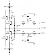
In order to have both sides of the bridge work in tandem, some 'connection' must be made between points C, D, +Sense, -Sense and Out_Bus.
But because the phases of the bridge outputs are opposite, these five signals per bridge side must be inverted and applied ('added' somehow) to the other bridge side and vice versa.
This can however lead to other issues which are unknown for now and should be addressed with labourous research. From this point onwards, I conclude that the initial 'classic' topology of (opamp-like) main amplifiers is not suitable for bridging, or various measures and control circuits are needed as shown in the annex of #22.
It can be done, but there is a more straightforward solution. A 'interwoven' (opamp-style double inverter amplifier with pos and neg output) bridge amplifier is a good solution. I'll try to find my design of it in my archives.
Attachments
- Home
- Amplifiers
- Solid State
- Do You Have a Solution for Bad Behavior of V-I Limiters in Bridged Amplifiers?