You are right. I did not describe this well. If the limiter is strong enough, the two loops fight until the VAS runs out of current to drive the output stage. It's a kind of equilibrium 🙂.I doubt this seriously. Two loops of a completely different kind in harmony? The feedback loop keeps driving the amp to its desired setpoint no matter what, the limiter undermines it until release. The strongest win, bending or bursting.
The most simple way to achieve loopgain control by a limiter I can think of now is to add mosfets in series with the reference resistor of the feedback loop networks (both sides of the bridge!) and lowering the closed loop amplification. Maybe such a circuit is in the Peavey?
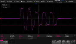
Attached is a scope screen shot from the SOA protection test of my latest mono block power amplifier (300 W / 4 ohms) . The SOA protection includes a "natural current limiter" per Bob Cordell to provide rapid and clean limiting until the slower V-I limiter kicks in. The V-I limiter is dual slope - one for above ground and a different one for below ground. The test waveform into the amplifier (gain = 20) was a 4 Vpp, 5 cycle burst of 10 kHz sine wave within a 100 ms period. The amplifier load was 1 ohm. The first cycle shows the clipping provided by the "natural current limiter." The amp puts out 28-30 A into a 1 ohm load for the first cycle. The second cycle shows distortion from the V-I limiter starting to kick in. By the 4th cycle, the V-I limiter has stabilized with the peaks limited to ~ +18 A into the 1 ohm load. Although there is over/undershoot and some slope across the tops and bottoms, it is fairly clean. The waveforms look much better at lower frequencies. This is a pretty severe test. I do not have screen shoots for reactive loads.You really need to see VI limiter waveforms to understand it.
Seeing is believing! 🙂
Attachments
Do you have a 1 ohm speaker I could borrow? 🙂Try it with a speaker.
Oh, I forgot, the measurement was made after the output L-R network (1 uH // 2.35 ohms) so there was a tiny bit of reactance in the circuit.

Yes.
The BIG one, who triggers VI protection like crazy (for very good reason), is at the low frequency resonance.
You have a big heavy cone, (say 50-70 grams of higher, including voice coil) moving half an inch back and forth, pushing/pulling that big voice coil through a STRONG magnetic field, it will generate lots of current, impressive voltage spikes is suddenly open or shorted, it is a big motor-generator, alternating between both along a single cycle, let alone during a musical passage.
Said voltage and current will be out of phase by as much as 60 degrees, which means it will simultaneously be passing current and getting/generating voltage, out of phase.
Now the speaker will not suffer by itself (think of reactive power, besides the resistive component of course), but will try to destroy semiconductors connected there.
Typically reverse biased diodes are used in parallel with output devices, to at least clamp voltage spikes to rails, more important to avoid reverse biasing which is deadly.
I guess this means the amplifier has to be left in linear range/mode and limiting done to the input signal.
I looked at going fully differential on my last power amp but decided that I would need common mode as well as differential feedback loops and it was getting complicated - lots of parts. I didn't study your schematic long but I'm thinking that it is stable because all of the loads are resistive, defining the voltages and currents. Is this correct? Seems like it might also require balanced power supplies? Why do you say no safeties required? Even in a full-up version capable of driving speakers?Symmetrical differential front stage, and a double Sziklai output: the Hiraga Bridge.
Named after Jean Hiraga, to honour the master.
This is my 'small exercise' design, somesort proof of concept of an 'interwoven' balanced bridge design.
Open loop bandwith (in simulation) close to 100kHz.
No rocket technology involved.
Bonus: no balanced input signal needed.
Extra bonus: no popping, no safeties needed.
Goal is to omit Q23, Q24, Q33 Q34 and replace Q21, Q22, Q31, Q32 with low output impedance ('v-fetish') compounds on which I'm working now (very promising).
The greatest advantage of the Hiraga is its intrinsic simplicity. The only thing I did was to exchange the single ended input stage for a symmetrical differential input stage. While doing the neccessary simulations, it occurred to me that while examining unbalanced input signals, the outputs remained symmetrical (the Spice response plot). Further ac simulations showed a very boring bandwidth respons, no nasty poles seemed to appear in the hf region. The open loop analysis was comparable, and no funny dips or peaks either. Even more boring, slopes 20dB/dec, phase in extremes to -90º (simu's, sure...don't trust them!). Then the more advanced dc analysis: starting up and shutting down. Only when one rail lags considerabe behind the other, an odd output swing and a protection relay will be needed. The simulated supply was from a rectified ac source, with coils, caps, coils and caps (LCLC). Like the original Hiraga, it is not very much susceptable to rail unbalances. As long as the input differentials starts up and shuts down synchronious, the output remains nearly at zero. Simulations are not to trust here so currently a build is in progress (BC550/560, BD139/140, TTC5200/TTA1943), some 20W/8Ω aiming. Selecting high beta 139/140 permits a second leg increasing current capability. It's going to drive 50W planars.I looked at going fully differential on my last power amp but decided that I would need common mode as well as differential feedback loops and it was getting complicated - lots of parts. I didn't study your schematic long but I'm thinking that it is stable because all of the loads are resistive, defining the voltages and currents. Is this correct? Seems like it might also require balanced power supplies? Why do you say no safeties required? Even in a full-up version capable of driving speakers?
I cannot devise another kind of appropiate safety measure (I have designed a simple dc detector cast somewhere on a forum here, that might come handy), as most are designed for classic designs (like your I-V imiter).
I forgot almost to answer your other question: all loads are resistors indeed (and no mirrors!) - I'm curious how the real thing will do with the miller caps.
Oh, no pcb design but a large striped test pcb, the diff-bjt's 2" apart, the diffs at 6" (I'm not following rules), long jumpers and other wiring mid air.
I doubt that this topology can output more then 100W, so very different from your systems and experience. But it was about the (not) use of protection and limiters specific.
Glad to hear that you are breadboarding it. Nothing beats real hardware! Please keep me informed on your progress.Simulations are not to trust here so currently a build is in progress (BC550/560, BD139/140, TTC5200/TTA1943), some 20W/8Ω aiming.
Slow due to personal matters and the build of a curve tracer. But don't be limited (!), and apply it to your own needs!
Small world 😱How about a realtime safe area usage display to help the thing at the end of the volume knob?
A friend of mine lost a lot of time and money trying to design and tune the "ideal" protection in his opinion: "a protection where power transistors reach just the SOA limit but never surpass it", so in theory providing maximum output possible, in a safe way.
Guess what?
His amps worked worked worked worked BOOM! time and time again.
Same basic idea.
A dangerous game. The published SOA curves are typical and only valid at one temperature. Some, like the popular NJL3281/NJL1302 don't even specify a continuous curve, just various pulse durations. You need margin.A friend of mine lost a lot of time and money trying to design and tune the "ideal" protection in his opinion: "a protection where power transistors reach just the SOA limit but never surpass it", so in theory providing maximum output possible, in a safe way.
Yes.
He made a circuit which detected real time voltage drop across and current through a semiconductor and he expected would detect second breakdown (literally) when starting.
His theory was that "if I can clamp transistor within a millisecond, that is not long enough to cause damage".
He got angry when I suggested that was akin to having a gyroscope in a backpack or belt pack, then walk along a precipice edge, and use gyro detected rate of angle change to detect when you were actually falling into the abyss, then trigger some safety measure.
Same thing 🙄
He never accepted my point of view but after a year he quietly left the project aside.
I guess it was getting expensive.
RCA had an app note (in the early years) for a non-destructive second breakdown tester. It worked by detecting a rapid drop in Vbe at the onset of second breakdown. But it has a LOT of emitter degeneration and operated within microseconds.
In an audio amp, you can’t have 12 to 15 volts of drop in the emitter resistors. Nor can you make a VI limiter activate in microseconds. When you make one that DOES act that fast, it almost always results in severe instability and oscillation when activated. You always end up intentionally slowing it down for stability, so the local feedback of the limiter isn’t fighting the global feedback of the amp in a vicious circle. It won’t be fast enough to prevent damage from second breakdown when it is actually occurring - you need to limit at a lower current and not wait for it to happen and try to stop it.
In an audio amp, you can’t have 12 to 15 volts of drop in the emitter resistors. Nor can you make a VI limiter activate in microseconds. When you make one that DOES act that fast, it almost always results in severe instability and oscillation when activated. You always end up intentionally slowing it down for stability, so the local feedback of the limiter isn’t fighting the global feedback of the amp in a vicious circle. It won’t be fast enough to prevent damage from second breakdown when it is actually occurring - you need to limit at a lower current and not wait for it to happen and try to stop it.
When you live on the edge, sometimes you fall off. 🙂He never accepted my point of view but after a year he quietly left the project aside.
I guess it was getting expensive.
Agree. That's why in my most recent PA I combined a V-I limiter with a "natural current limiter" à la Bob Cordell. Have you, or any of the others on this thread played with the latter? It's really awesome. It is just one clamp diode from each end of the bias generator to the output rail. Since it is a clamp and not a feedback loop, it is almost instantaneous with no over shoot, and no compensation required. The only downside is that it is not very flexible.Nor can you make a VI limiter activate in microseconds. When you make one that DOES act that fast, it almost always results in severe instability and oscillation when activated. You always end up intentionally slowing it down for stability, so the local feedback of the limiter isn’t fighting the global feedback of the amp in a vicious circle.
A curve tracer! Are you going to buy in bulk and match transistors for your designs? That's pretty hard core! 🙂Slow due to personal matters and the build of a curve tracer. But don't be limited (!), and apply it to your own needs!
- Home
- Amplifiers
- Solid State
- Do You Have a Solution for Bad Behavior of V-I Limiters in Bridged Amplifiers?