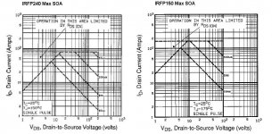
I just checked with our only local shop in town but IRFP150 is missing, on the other hand they have IRFP240 so I'm wondering could I use it instead, see attached picture of Maximum Safe Operating Area for both FET's if that helps.
X when you trim the 500 Ohm trimmer CW, does that mean the trimmer wiper (center leg) goes towards the one end where the 2,5 kOhm trimmer is connected, and vice verse, CCW is when the wiper goes towards the Gate of the output FET?
X when you trim the 500 Ohm trimmer CW, does that mean the trimmer wiper (center leg) goes towards the one end where the 2,5 kOhm trimmer is connected, and vice verse, CCW is when the wiper goes towards the Gate of the output FET?
Attachments
Last edited:
My amp uses IRFP240 - works fine and readily available like tap water. I will have to look at my pots to see what way the CW and CCW are set. However, if you orient them as I have in my photo it should be consistent. Although it's of no consequence as you simply go the other way. Although without measurement you won't know I suppose. Let me get back to you.
My pot is labeled and wired such that when the turned CW, the value presented between top pin (3)/wiper (2) which are connected together, and lower pin (1), is that the overall resistance increases. Standard Bournes 3296 (actually a Chinese "Bonens" clone - don't flame me, they work just fine at $3 for a bag of 20) pot.
Similar to this:
https://www.westfloridacomponents.com/mm5/graphics/ds/3296.pdf
Similar to this:
https://www.westfloridacomponents.com/mm5/graphics/ds/3296.pdf
Thanks a lot X, good to hear IRFP240 will work!
I must be a bit slow today... did you say you connected the 500 Ohm trimmer leg 2 and 3 together, please check attached picture.
This may also be reason why the offset starts to wander when adjusting the SE/PP trimmer?
I must be a bit slow today... did you say you connected the 500 Ohm trimmer leg 2 and 3 together, please check attached picture.
This may also be reason why the offset starts to wander when adjusting the SE/PP trimmer?
Attachments

did you say you connected the 500 Ohm trimmer leg 2 and 3 together, please check attached picture.
This may also be reason why the offset starts to wander when adjusting the SE/PP trimmer?
Attached Thumbnails
I sure did! Doh! That's what happens when you layout PCB's by hand marker in the wee hours of the morning. 🙂
I will take an xacto to it then - but I assume this may completely change the bias setting. Maybe I will leave alone for now and just enjoy it 🙂
Thanks for pointing that out.
Oy vey! 😛
Yes it looks like to affect the bias as well as the overall resistance decreases, I wonder now how much that did with the decreasing H2 distortion in your earlier FFT measurements, anyway now it's time for a break over here too, and tomorrow am heading over to our local candy boutique collecting some goodies! 🙂
Cheers Michael
xrk971 DLH Layout
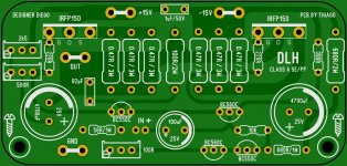
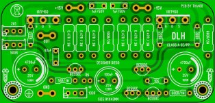
Here is my layout if anyone wants to try it. It conveniently matches the budget phenolic copper faced boards on Aliexpress/eBay (measures 97mm x 70mm).
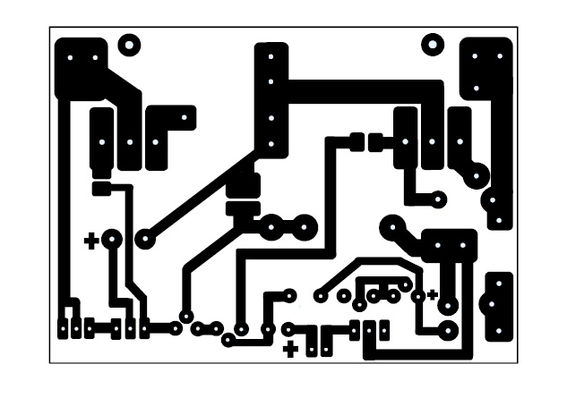
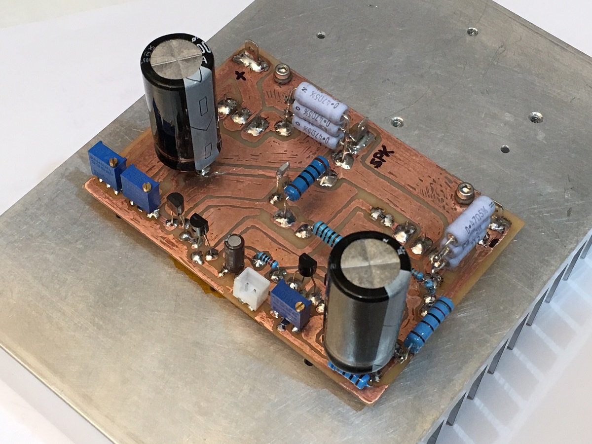
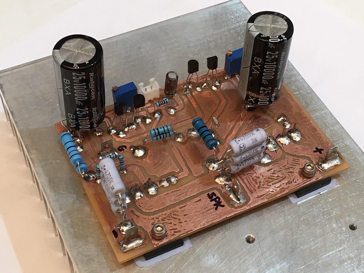
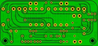
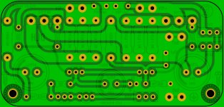
Placement of parts just follow this photo - pretty easy actually. You can also choose to put copper on bottom side like traditional PCB and have through hole parts on top.
Here is my layout if anyone wants to try it. It conveniently matches the budget phenolic copper faced boards on Aliexpress/eBay (measures 97mm x 70mm).
Placement of parts just follow this photo - pretty easy actually. You can also choose to put copper on bottom side like traditional PCB and have through hole parts on top.
Attachments

Last edited:
I have been thinking about what X commented about the modification of the bias current with the position of the 500 ohm trimpot cursor.
That should not happen.
One of the possibilities: he set up a bootstrap capacitor of 10000 uF associated with this trimpot (technically not bad, quite the contrary). The establishment of the permanent bias current may take quite some time between each setting. I would suggest checking values after 70-80 seconds between successive settings. The readings may have been taken in less time, this could be during the transient.
In the case of X, since the capacitor is larger, that time should be longer (probably 150 seconds).
regards
I think it's because I miswired the trimpot. I connected the wiper to the upper leg but wiper should not have been connected to upper leg.
Member
Joined 2009
Paid Member
Bigun: Could you quote links from Hugh Dean and Broskie posts?
Regards
Hi Diego,
The link for Broskie... Class-A & Current-Dumping & Class-S .... you have to scroll down.
I never tried it. But my JLH amplifier (I called it TGM9) doesn't sound as good as I had hoped. Perhaps I should try to reconfigure it using your circuit !
Last edited:
I think it's because I miswired the trimpot. I connected the wiper to the upper leg but wiper should not have been connected to upper leg.
If so, it has an easy solution. Anyway, your amplifier has given spectacularly good numbers
 . It's time to put it in a nice cabinet and enjoy it for a long time
  .
.Thank you a lot
Hi Diego,
The link for Broskie... Class-A & Current-Dumping & Class-S .... you have to scroll down.
I never tried it. But my JLH amplifier (I called it TGM9) doesn't sound as good as I had hoped. Perhaps I should try to reconfigure it using your circuit !
Thanks for the link. I had already seen that page. Broskie has admirable works, although he did not take full advantage of the four (4) terminals of the bastode (like NAD people and others). Those designs are cousins of my design. Mentally they took the bastode and used the same amount of terminals that are normally used in an LTP (only three (3)).

The fourth terminal adds a lot of technical potential to the circuit
regards
Last edited:
Member
Joined 2009
Paid Member
Is it possible to change the Output Mosfets to say IRFP264, increase supply voltage for a higher output into 8 ohm loads?
Irfp250, 244, 240, 150, 140.
Are all appropriate.
Irfp264 would still certainly work but maybe not optimally.
Are all appropriate.
Irfp264 would still certainly work but maybe not optimally.
Thank you 2 pico... I am just looking at parts which are rated above 250watts to maximize dissipation. What higher voltage would be safe to get about 10-15 watts into an 8 ohm load? Thanks in advance.
I am quite happy running all those devices at 35W each.
20V rails at 1.5A would certainly be ok.
You just need the appropriate heatsinks, and transformer VA rating.
20V rails at 1.5A would certainly be ok.
You just need the appropriate heatsinks, and transformer VA rating.
- Home
- Amplifiers
- Solid State
- DLH Amplifier: The trilogy with PLH and JLH amps