DLH Measurements
Diegomj:
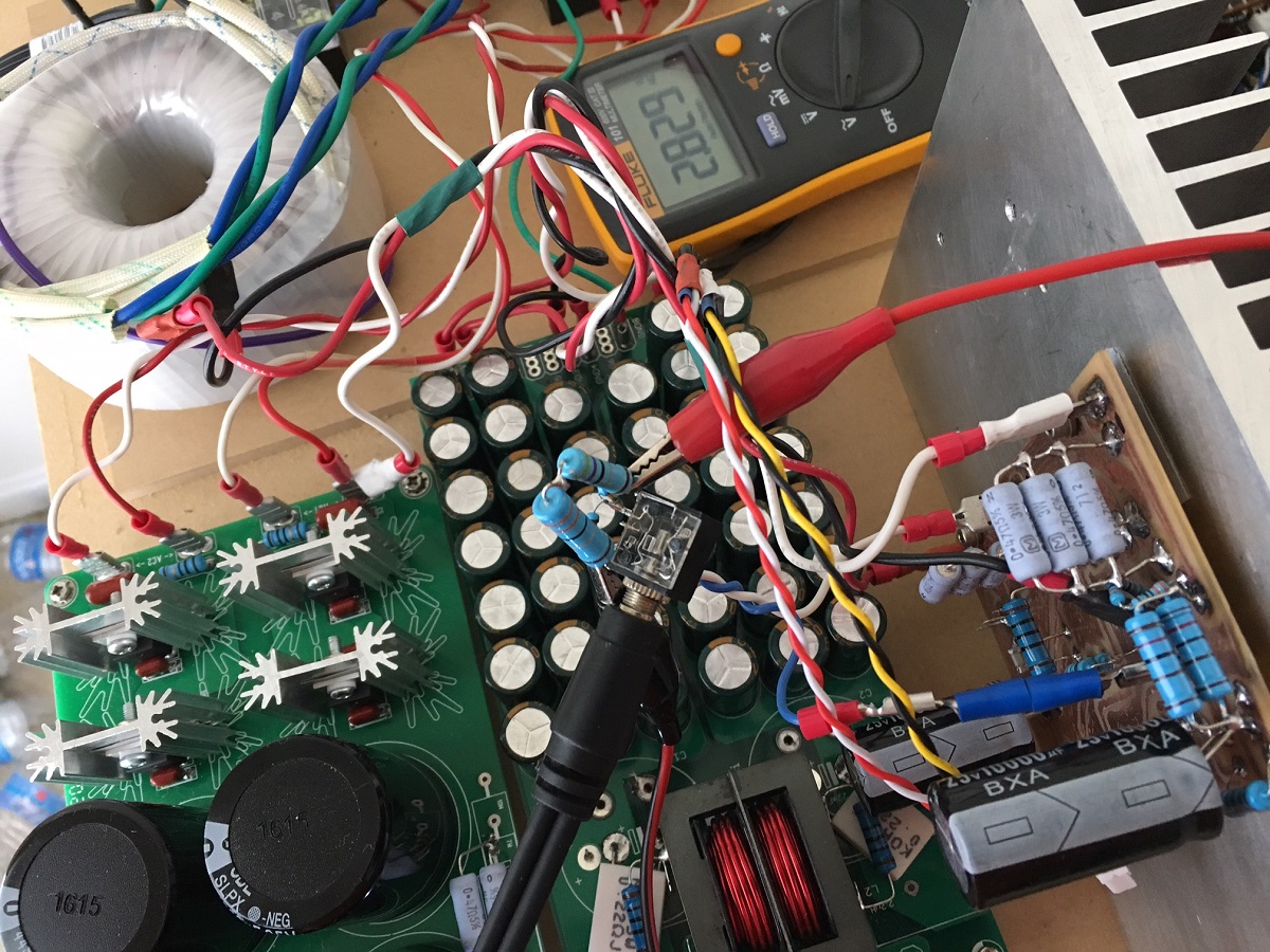
You will be pleased to hear that your amp is a brilliant performer! I set it up to drive an 8.00 ohm (4.7R + 3.3R 1% metal thin film resistors in series) load at 2.83V RMS (as measured with Fluke 101), and measured through a 1:10 resisitive divider (2k2 and 20k resistors) and measured with the ADC on my Focusrite Solo sound interface.
THD is 0.0021% with H2 at 0.0019% and H3 at 0.00087% and nothing else. Noise floor is very quiet. Most of the noise below 1khz is my linear power supply ripple and harmonics getting through. Noise floor is at limit of my measurement device ~-130dB. Signal only shows -20dB due to the 1:10 divider to protect the input preamps on the ADC:

The frequency sweep is also excellent, showing a mild rise of 9dB in THD with increasing frequency from 1kHz to 10kHz:

Overall, an excellent measuring amp and you should be proud of it!
Thanks for the super amp design.
Cheers,
X
p.s., when I have time, it will be VERY interesting to see the FFT in real time as I adjust that SE/PP pot! 😀 Measurement above with the pot set at the recommended level on the schematic.
Diegomj:
You will be pleased to hear that your amp is a brilliant performer! I set it up to drive an 8.00 ohm (4.7R + 3.3R 1% metal thin film resistors in series) load at 2.83V RMS (as measured with Fluke 101), and measured through a 1:10 resisitive divider (2k2 and 20k resistors) and measured with the ADC on my Focusrite Solo sound interface.
THD is 0.0021% with H2 at 0.0019% and H3 at 0.00087% and nothing else. Noise floor is very quiet. Most of the noise below 1khz is my linear power supply ripple and harmonics getting through. Noise floor is at limit of my measurement device ~-130dB. Signal only shows -20dB due to the 1:10 divider to protect the input preamps on the ADC:
The frequency sweep is also excellent, showing a mild rise of 9dB in THD with increasing frequency from 1kHz to 10kHz:
Overall, an excellent measuring amp and you should be proud of it!
Thanks for the super amp design.
Cheers,
X
p.s., when I have time, it will be VERY interesting to see the FFT in real time as I adjust that SE/PP pot! 😀 Measurement above with the pot set at the recommended level on the schematic.
Attachments

Last edited:
Wow 😱😱😱!!!. How impressed I am with the perfect work you've done!
Wow wow wow 😱😱😱!!! Still more impressed with the results of the measurements!
Probably, the 500 ohm trimpot is not yet in position to get the lowest possible distortion !!!.
Congratulations and again thanks for all your great work !!! 😉🙂.
Wow wow wow 😱😱😱!!! Still more impressed with the results of the measurements!
Probably, the 500 ohm trimpot is not yet in position to get the lowest possible distortion !!!.
Congratulations and again thanks for all your great work !!! 😉🙂.
My ears prefer a little H2 and maybe a tiny bit H3 - very much like what is here already. Probably even a tad more H2 would be preferred in blind listening tests. However, to each his own, and perhaps that's what is nice about this amp: adjustable "sweetness" knob. 😀
You are welcome Diogomj! Thank you for the nice amp design! It's rare to see a distortion profile like this except from quasi singleton amps. It goes to show that wonderful results are possible with very few actives. Almost seems like a conspiracy by transistor companies to sell more transistors by promoting high actives count amps. 🙂
This amp is definitely a keeper and possibly will get its own proper case one day.
Last edited:
Wow that's very impressive X, the amp meassures very well, to such a degree even I feel now very compelled building it.
I just found out having a toroid sitting around here collecting dust with a pair of 18 VAC windings 60 VA each, would that be ok or is it a tad too high V?
I just found out having a toroid sitting around here collecting dust with a pair of 18 VAC windings 60 VA each, would that be ok or is it a tad too high V?
I will give it a try, otherwise it's always easy adjusting the voltage a bit with a few auxiliary windings manually added to subtract or add voltage, have done it before and one of the great advantages using toroids! BTW what hfe class are those BC550/560's A, B or C??
It is preferable to use BC5XX with suffix C, in order to increase the precision of the phase splitter.
It is highly recommended that the hFE value of the BC550 is not less than 50% of the hFE value of the BC560. If the hFE value of the BC550 exceeds the hFE value of the BC560, there is no problem.
The greater precision of the phase splitter is one of the great advantages that this design has over the design of John Linsley Hood (unless you make certain adjustments to the JLH). This allows to operate in push pull mode with greater precision, reflecting in very low rates of distortion.
regards
PD: other beautiful PCB, thiagomogi!!!. Thanks you very much!!!.
Last edited:
Very nice Thiago. I don't know how necessary they are, but I added 220R gate stoppers on the MOSFETs.
I am listening in pseudo stereo (one amp to both ears) with my 55ohm OB-1 headphones now, and must say, this is an excellent headphone amp as well. Absolutely quiet - no hum, hiss, or otherwise noise. Great powerful bass and super dynamics. Very transparent and revealing. Very few speaker amps are quiet enough to be headphone amps. At least I know my PSU and grounding is good.
Last edited:
Effect of adjusting the SE/PP distortion pot
The amp does indeed have a variable harmonic distortion profile adjustment knob. Turning the pot clockwise (CW) tends towards higher H2 (and higher overall THD) and less relative H3 for a more "SE" profile, and turning it (CCW) tends towards lower THD and more H3 relative to H2 for a more "Push-Pull" profile. At one point, the H3 will even be higher than the H2. I took data at various positions relative to the baseline setting (51% of the 500R pot). At some point, I accidentally started counting half revolutions, so don't hold me to it. 🙂 But, you get the idea. I will try listening at the SE mode more as that is my preference.
Starting at the SE end (CW) of the spectrum and going to the PP end (CCW), we get the following progression for 2.83vrms into 8ohms:


So there you have it, dial-a-yield "sweetness" vs "bite" knob. 🙂
The amp does indeed have a variable harmonic distortion profile adjustment knob. Turning the pot clockwise (CW) tends towards higher H2 (and higher overall THD) and less relative H3 for a more "SE" profile, and turning it (CCW) tends towards lower THD and more H3 relative to H2 for a more "Push-Pull" profile. At one point, the H3 will even be higher than the H2. I took data at various positions relative to the baseline setting (51% of the 500R pot). At some point, I accidentally started counting half revolutions, so don't hold me to it. 🙂 But, you get the idea. I will try listening at the SE mode more as that is my preference.
Starting at the SE end (CW) of the spectrum and going to the PP end (CCW), we get the following progression for 2.83vrms into 8ohms:
So there you have it, dial-a-yield "sweetness" vs "bite" knob. 🙂
Last edited:

Thanks Zman,
It's a fun sounding little amp with the dial-a-yield pegged to the SE camp. 😀 My one complaint, true of all SE Class A amps - it makes heat like nobody's business. 🙂 This sucker runs hot for a 15v rail amp. I guess I don't have any previous amps that run at 1.8amps bias. I may try reducing that now to get the heat down and see what that does to THD and H2/H3....
Edit: so the above experiment of adjusting the sweetness knob also affects the bias. I just measured the bias with the amp pegged at the SE mode and it is only 0.87A and the rails have accordingly risen to 17.4v due to the lower demands. I suppose a more careful experiment would require iterative adjustments to maintain constant bias at different settings but I am too lazy to do that. So keep in mind that the DC offset drifts with the sweetness knob as well so they are not all independent changes. I was at 167mV DC offset but that was easily adjusted back to 0mV with a half turn on the pot.
So I readjusted the bias up to 1.05amps for a good tradeoff with heat.
Last edited:
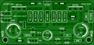
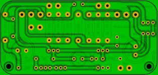
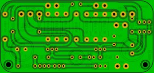
91x43mm
Very nice Thiago. I don't know how necessary they are, but I added 220R gate stoppers on the MOSFETs.
Attachments

Hugh is correct,
Very nice Thiago! 🙂 Can we please have the (mirror image) pdf's & Gerbers? What are the board dimensions?
Thank you,
X
noticed that you have "DHL" instead of DLH
Just make the PCB with yellow solder mask and red silkscreen! 😀
- Home
- Amplifiers
- Solid State
- DLH Amplifier: The trilogy with PLH and JLH amps