Balanced output ES9018K2M
The 9018k2m has differential (balanced.) output.
DIYINHK use an I/V converter with SE output, actually this is an bal/SE converter I/V stage.
Don't use an another converter to make differential output again!
Fig1. is simple, cheap, and it has good performance.
Hi Rookakoma
Thanks for your post.
I am a novice!!😕
On the backside of the board I see "+DACR-" and "+DACL-". Are these the balanced outputs. Can I easily use these to connect balanced XLR-outputs?
Which ground should I use, 3,3V or 12V?
Joris
Hi Jokanok,
"+DACR" and "+DACL-" are right and left channels(connected directly to the 9018k2m). You can use them for balanced outputs
I think that it is best to use GND from 3,3 V, described previously.
Regards
"+DACR" and "+DACL-" are right and left channels(connected directly to the 9018k2m). You can use them for balanced outputs
I think that it is best to use GND from 3,3 V, described previously.
Regards
Thanks for the input gostar123.Hi Jokanok,
"+DACR" and "+DACL-" are right and left channels(connected directly to the 9018k2m). You can use them for balanced outputs
I think that it is best to use GND from 3,3 V, described previously.
Regards
Another noob question.
If I use digital volume control, will the balanced XLR-outputs also output the amplified/attenuated analog audio signal?
Joris
Hi Jokanok,
I suppose that digital volume control will behave as you expect. I am Using Amanero USB to I2S converter and have no digital volume control.
I suppose that digital volume control will behave as you expect. I am Using Amanero USB to I2S converter and have no digital volume control.
Driver Signing
I just saw this post, a few months old, but I haven't seen an answer so for those that could run into this.... On Windows 10... Go into advanced settings and Disable
"Driver Signing" Re down load and you'll have your driver...
I hope this helps, Tim
Have somebody tried to install drivers for Win 10? I've tried today, the process of installation is completed successfully, but got an error in device manager "Indicates two revision levels are incompatible" with code 10. :-(
XMOS works properly with Win 7 at my laptop.
I just saw this post, a few months old, but I haven't seen an answer so for those that could run into this.... On Windows 10... Go into advanced settings and Disable
"Driver Signing" Re down load and you'll have your driver...
I hope this helps, Tim
Hi gostar123. Did you do the connection with the Bronskey Unbalancer? I am starting exactly the same build so would appreciate any guidance you can provide.Hi,
has anyone connected this DAC differential outputs to Broskie Cathode Follower of The Unbalancer ?
Any pointers ?
made a shunt noise filter based LM317 reg 3.3v pair PSU
and 12+/- supply capacitive kmultiplier PSU and connected to the DAC boards
Soldered the wires to 3.3V lines and 12v pins.
after power up i see 44.1khz LED blinking
But there is no USB device detection
Do we need to give 3.3v to the XMOS seperately?
and 12+/- supply capacitive kmultiplier PSU and connected to the DAC boards
Soldered the wires to 3.3V lines and 12v pins.
after power up i see 44.1khz LED blinking
But there is no USB device detection
Do we need to give 3.3v to the XMOS seperately?
Approx. two months ago I finally managed to finish the first part of this project:
A generic view (the dac is the first device):
The internals of the DAC:
In general I am very much satisfied, although I am really interested in any suggestion of an additional iv stage that could be a part of this assembly.
A generic view (the dac is the first device):
An externally hosted image should be here but it was not working when we last tested it.
The internals of the DAC:
An externally hosted image should be here but it was not working when we last tested it.
In general I am very much satisfied, although I am really interested in any suggestion of an additional iv stage that could be a part of this assembly.
I am using the DIYINHK isloated USB tro I2S board. It works perfectly with FooBar, following the instructions provided on the DIYINHK web site. And it sounds good. Playing DSD via DoP is a very satisifying experience, the closet that I have heard digital get to analog.
But has anybody been able to get this board running with JRiver? I am also using Pono Music World (PMW) at home (only becuase I bought a Pono player). Using my internal sound card (EMU1212M), PMW sounds better than FooBar. So, I would like to compare FooBar to PMW through the USB board. But I can't figure out how to configure PMW. PMW is simply a stripped version of JRIver (no video) so i assume that all the audio config is identical to JRiver. I asked DIYINHK support, but they advise that they don't have a version of JRiver.
So, has anybody else out there been able to play JRiver through the DIYINHK board? If so, what is the configuration?
BTW - i need to play everything as DSD (DoP). I can't play PCM through the USB Board. I know that the board is capable of PCM, but I'm not using a DAC... So I want to play DSD files on PMW, and also convert PCM to DSD before I send it to the USB board. That is how I am doing it with Foobar - send DSD as DoP, and convert PCM to DSD. Its easy in FooBar. How do I do this in PMW/ JRiver??
Thanks, Hazard
Last edited:
I just saw this post, a few months old, but I haven't seen an answer so for those that could run into this.... On Windows 10... Go into advanced settings and Disable
"Driver Signing" Re down load and you'll have your driver...
I hope this helps, Tim
Thanks Tim, your tip really helps. I installed up-to-date build of Windows 10 several days ago, and it works for me now.
made a shunt noise filter based LM317 reg 3.3v pair PSU
and 12+/- supply capacitive kmultiplier PSU and connected to the DAC boards
Soldered the wires to 3.3V lines and 12v pins.
after power up i see 44.1khz LED blinking
But there is no USB device detection
Do we need to give 3.3v to the XMOS seperately?
If you use galvanic isolation option, you need to supply power separately. If you connect it to Diyinhk DAC, the power supply is on the dac board and feeds xmos chip and clock.
Regards, Konstantin
But has anybody been able to get this board running with JRiver?
So, has anybody else out there been able to play JRiver through the DIYINHK board? If so, what is the configuration?
Thanks, Hazard
Hi Hazard, I use it with Jriver. Standart configuration - just choose your device from drop-down list, that's it. I use wasapi option - as a default. Asio is also available in the list to choose.
BTW - i need to play everything as DSD (DoP). I can't play PCM through the USB Board. I know that the board is capable of PCM, but I'm not using a DAC... So I want to play DSD files on PMW, and also convert PCM to DSD before I send it to the USB board. That is how I am doing it with Foobar - send DSD as DoP, and convert PCM to DSD. Its easy in FooBar. How do I do this in PMW/ JRiver??
Thanks, Hazard
Yes, it is possible. You can set up a conversion from PSM to DSD for all the supported formats. Guess, small differences from foobar in this regard.
Well maybe I'm just stoopid or something happened in the new release of PMW I got today. I got home tonight, opened Pono Music World and saw there was an update so I updated (20.0.100). I then went through the config as you describe above. Some of the options in the config have changed but all I had to do was select device - DIYINHK USB (Asio) and in DSP menu I selected output as DoP. And guess what - it works perfectly. I don't think I did anything different to before but who knows. In any case, thanks for your reply.Hi Hazard, I use it with Jriver. Standart configuration - just choose your device from drop-down list, that's it. I use wasapi option - as a default. Asio is also available in the list to choose.
If you use galvanic isolation option, you need to supply power separately. If you connect it to Diyinhk DAC, the power supply is on the dac board and feeds xmos chip and clock.
Regards, Konstantin
mailed the supplier he says the current is not enough ..I will make one basic PSU with lm1117 to give the 3.3v . May be my way of doing it is wrong '
I have the kmultiplier and fed the +12V to the 3.3V circuits and that is not pulling enough current .
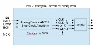
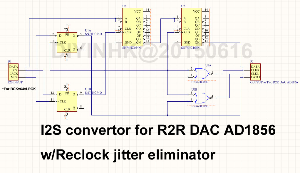
I2S to ESC (EIAJ STOP CLOCK) PCB to R2R DAC with schematic
Dear all friend,
I am playing on the famous AN207 stop clock operation,
To verify it's work like it should be.
I compose an i2s data stream to test
The left channel is 16bit 1010101010101010
the right channel is 16bit 1010110011001010
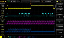
the timing from the oscillscope looks perfect,
There are BCK after the WCK go low latch signal.
it should meets the PCM1704 stopped clock operation requirement
Let me test it on as more R2R DAC as before release😱
Dear all friend,
I am playing on the famous AN207 stop clock operation,
To verify it's work like it should be.
I compose an i2s data stream to test
The left channel is 16bit 1010101010101010
the right channel is 16bit 1010110011001010
the timing from the oscillscope looks perfect,
There are BCK after the WCK go low latch signal.
it should meets the PCM1704 stopped clock operation requirement
Let me test it on as more R2R DAC as before release😱
Attachments
Last edited:
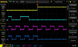
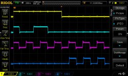
Yellow: LATCH for left and right DAC
Cyan: DATA for left and right DAC
Purple: Right clock
Blue: Left clock
The original design uses NAND gate, the left clock has ~20ns delay to the right clock when using 74HC logic, it can be read from the above oscilloscope capture.
R2R IC like AD1856 is output on the falling edge of latch signal, not based on BCK, this delay will not causes problem. For PCM1704, the output is on the second bck following the latch signal, the delay on the left and right clock will causes 20ns different on the left and right channel, it's smaller than 1/100 phase different even at 384khz sample rate, although I doubt it is listenable, but there is never an enough for people in here. The design is just revised to sync the left right clock and eliminated the nano second level output delay.
Last edited:
DONE!
Welcome to build and try yourself!
The schematic is free for personal use!
The serious shortcoming of the original AN207 is it do not has reclock and it assumes BCK=32xLRCK from the i2s source. But nowadays, all I2S source is BCK=64xLRCK.
The below circuit is not only verified by ear and it is also verified by oscilloscope using a composed i2s data stream to guarantee the output is bit perfect and jitter free. The information for how to compose an i2s stream can be found here.
http://www.diyaudio.com/forums/digi...eam-verify-real-bit-perfect-oscilloscope.html
spdif
If you do not need to switch between i2s and spdif, the es9018k2m can work only in spdif mode, the spdif will need to be connected to the 20 pin header labelled BCK
this is what I've received from diynhk about spdif:Hi
I am very tempted to order the full DAC (DAC, USB receiver and power supplies) but I also need to be certain if I can connect simultaneously the USB receiver and a Toslink input.
On the DIYINHK website is stated that the input labeled "SPDIF IN" can be used to directly connect a SPDIF optical receiver(Toshiba TORX147 or equivalent).
However the pictures published on the DIYINHK-website are not clear in this regard. I think the picture of the backside of the board does not conform with the picture of the upside, and I also cannot see how the Toslink could be directly connected to the DAC-board.
I send DIYINHK a mail raising the exact same question.
When I receive a clearcut answer, I will certainly post again.
Did you in the meantime found the answer?
Joris
If you do not need to switch between i2s and spdif, the es9018k2m can work only in spdif mode, the spdif will need to be connected to the 20 pin header labelled BCK
For 3,3V power supply, I don't know what to choose between
4.17uV Ultralow noise DAC power supply regulator 3.3V/5V 1Ax2 - DIYINHK
and
4.17uV Ultralow noise DAC power supply regulator 3.3V/5V 1Ax2 - DIYINHK
Any advice ?
Thanks
4.17uV Ultralow noise DAC power supply regulator 3.3V/5V 1Ax2 - DIYINHK
and
4.17uV Ultralow noise DAC power supply regulator 3.3V/5V 1Ax2 - DIYINHK
Any advice ?
Thanks
For 3,3V power supply, I don't know what to choose between
4.17uV Ultralow noise DAC power supply regulator 3.3V/5V 1Ax2 - DIYINHK
and
1.0uV Ultralow noise DAC power supply regulator 3.3V 5.0V 800mA - DIYINHK
Any advice ?
Thanks
4.17uV Ultralow noise DAC power supply regulator 3.3V/5V 1Ax2 - DIYINHK
and
1.0uV Ultralow noise DAC power supply regulator 3.3V 5.0V 800mA - DIYINHK
Any advice ?
Thanks
- Home
- Vendor's Bazaar
- diyinhk Store