I have not tested many dacs but this one was a major improvement comparing to my beloved weiliang AK4399 (however it's still one of my favourites).
Hi tuxx,
can you please elaborate your statement more in detail? What exactly was major improvement? What AK4399 you use (single or dual, mods?). Why is AK4399 still one of your favorites if ES9018K2M is so much better?
I find 9018k2m much more detailed with bigger sound stage which is something I really like.
My 4399 is single with changed opamps I don't remember right now.
I stated that it's still one of my favorites because I believe that it's a killer for the money it costs and because I still enjoy it when I listen from this. It does not have the detail of 9018k2m but I could still live with this without any problem. Last but not least, my other dac is a 9023 from HiFimeDIY and 4399 is by far a higher class solution.
Sent from my Oneplus One
Last edited:
Hi all,
would it be possible to use this S/PDIF/ttl board to connect S/PDIF out to the ttl-IN of the Diyinhk-DAC?
Any simpler/cheaper solution? Preferrably ready-made.
Thanks!
Stephan
would it be possible to use this S/PDIF/ttl board to connect S/PDIF out to the ttl-IN of the Diyinhk-DAC?
Any simpler/cheaper solution? Preferrably ready-made.
Thanks!
Stephan
How to convert coaxial S/DIF to ttl-level input
Meanwhile, I found a couple of descriptions/schematics to convert S/DIF coax to ttl-level (listed below).
I would like to connect my PC via usb to the diyinhk-dac (ES918 K2M + XMOS) and my sonos connect I would like to connect via S/PDIF coax to the tt-in of the same dac (combo will be ordered once I sorted out this connection-question).
Maybe I could bulit this converter myself (on a stripboard)? But I would need the help of someone who gives me a hint which may be the best solution for my application.
Is a stripboard-approch a suitable solution at all? Or should one rather buy a ready-made board (see link in my previous post) or any other board/module/adapter? Any additional info is much appreciated (e.g. "additional or specific parts to be used?", which circuit below is best suited?).
I found the following versions:
So thanks a lot to anyone who cares to help me out here!
Stephan
Meanwhile, I found a couple of descriptions/schematics to convert S/DIF coax to ttl-level (listed below).
I would like to connect my PC via usb to the diyinhk-dac (ES918 K2M + XMOS) and my sonos connect I would like to connect via S/PDIF coax to the tt-in of the same dac (combo will be ordered once I sorted out this connection-question).
Maybe I could bulit this converter myself (on a stripboard)? But I would need the help of someone who gives me a hint which may be the best solution for my application.
Is a stripboard-approch a suitable solution at all? Or should one rather buy a ready-made board (see link in my previous post) or any other board/module/adapter? Any additional info is much appreciated (e.g. "additional or specific parts to be used?", which circuit below is best suited?).
I found the following versions:
- Version 1 of S/DIF coax to ttl S/PDIF Digital to Analogue Converter (Fig. 5 Appendix at the end of the page). But:
...😕This is as simple as it can get, and the circuit will not work correctly (if at all) if the levels are too low. Impedance matching is quite accurate, and it will load the transmitter to almost exactly +/-0.25V.
- Version 2a and 2b of S/DIF coax to ttl:link (page 7)
- Version 3a and 3b of S/DIF coax to ttl: whitefiles.org (two figures at the end of the page):
Under some circumstances you may want to convert an S/PDIF signal into a form that can be fed into a standard computer circuit at TTL levels. Here’s a simple solution, again using the 7HCU04 chip:-An externally hosted image should be here but it was not working when we last tested it.
whilst the simple circuit shown below includes an adjustment for DC offset, with the voltage on the ‘traveller’ of the preset normally set to around 2.6 volts.An externally hosted image should be here but it was not working when we last tested it.
So thanks a lot to anyone who cares to help me out here!
Stephan
Transformer coupled using a comparator chip works well.
Something like this from Twistedpear.
http://www.twistedpearaudio.com/docs/digital/spdif_1_schematic.pdf
Something like this from Twistedpear.
http://www.twistedpearaudio.com/docs/digital/spdif_1_schematic.pdf
Thank you, deanoUK!! That's even better than what I was hoping and looking for! Thank you so much!
Stephan
BTW, I spent two years at Birmingham Uni/Business School back in the nineties. Two of the best years of my life! 🙂
Stephan
BTW, I spent two years at Birmingham Uni/Business School back in the nineties. Two of the best years of my life! 🙂
Have somebody tried to install drivers for Win 10? I've tried today, the process of installation is completed successfully, but got an error in device manager "Indicates two revision levels are incompatible" with code 10. :-(
XMOS works properly with Win 7 at my laptop.
XMOS works properly with Win 7 at my laptop.
Transformer coupled using a comparator chip works well.
Something like this from Twistedpear.
http://www.twistedpearaudio.com/docs/digital/spdif_1_schematic.pdf
What IC is used by twistedpear?
maybe helpful with regard to transformer used by TP:
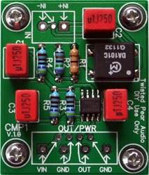
Image can be found here: The Buffalo III Digital-to-Analog Converter
Hope it's OK with TP to show it here.
Regards
Stephan
Image can be found here: The Buffalo III Digital-to-Analog Converter
Hope it's OK with TP to show it here.
Regards
Stephan
Just a word in case you feel like adding an external controller such as an Arduino later.
The bundled Xmos usb interface controls the digital volume in the DAC through the I2C bus (it uses the s/w volume control in your computer). If you wish to use an external controller for volume contro (such as using an Arduino), then you will have to purchase an Xmos interface that does not use the I2C bus such as this:
XMOS DSD DXD 384kHz high-quality USB to I2S/DSD PCB - DIYINHK
Thanks, glt, for this clarification.
I searched the thread and the diyinhk web page but couldn't find the answers I am looking for before I am ready to order.
I would like to connect 2 sources at the same time. A Sonos Connect via S/PDIF and a PC via the attached usb-board/I2S.
How can I switch between S/PDIF and usb input. Only via some external manual switch I would have to install? Or could I also do the switching with an external relay (board)? Is one of the sources automatically the default source?
So my question is, how does the switching work, exactly and what are the options to control it with this combo? In addition: can the DAC in this combo be controlled via software (e.g. arduino) just as the standard combo (with the exception of controlling the volume)?
If I don't care about DSD, and I want physical volume control (buttons/knobs rather than software controlled), can I use this Isolated 32bit 384kHz USB to I2S/SPDIF CM6631A PCB for the USB to I2S conversion? Will it "just work" or will either board require additional tweaking?
Hi all,
Need help in connecting Amanero USB->I2S output to ES9018 K2M DAC (diyinhk) I2S input.
What are the correct pin to pin connections ?
Need help in connecting Amanero USB->I2S output to ES9018 K2M DAC (diyinhk) I2S input.
What are the correct pin to pin connections ?
Hi all,
Need help in connecting Amanero USB->I2S output to ES9018 K2M DAC (diyinhk) I2S input.
What are the correct pin to pin connections ?
Amanero - 9018K2M
FSCLK- LRCK/D1
CLK-BCK
DATA -DATA/D2
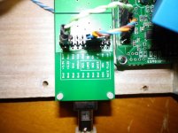
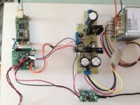
I have make this dac with 3 d-Reflector 3.3V Analog - 3.3V Digital - 5.0.V for Amanero and one Bib for 12V +/- for opamp.
Also need at output capacitor 10uf to zero dc offset 0.1mv and LPF filter to clean the output. Value for money this Dac .
No clicks, no pops, ready to run always .DSD 128 ,256 Flac 384 ALL FINE AND THE SOUND EXCELLENT.
Use sepate secondaries from transformer for eatch voltage supply 3.3Digital 3.3V Analog , 5.0V Amanero ,+/- 12V for opamp.
Also if you have old computer with XP Windows use the 1.56 driver for Amanero for clean volume for Foobar.
Attachments
Last edited:
Thank you nikosokey,
got it running. Sounds fine, from the dac using opamp. Want to further upgrade with Broskie Cathode follower for diff. outputs and not use opamp at all. Need to upgrade the better power supply for 3.3V.
Use Amanero with Jriver and Win 8.1 and no volume control so far. Must explore further.
Thanks again.
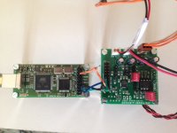
Did someone bought combination of ES9018 with isolated XMOS..
I wonder if there is a possibility that the input part of the XMOS is powered independently, not from computer..
Also, I wondered what the topology is used for analog output.. ES9018 datasheet has only version with three opamp output, and diyinhk claims that he use original output.. it would be good if someone has schematic.. did anyone experimented with opamp switching, is there any change..
 I think DIYINHK use similar like attached I/V stage.
This is the most simple solution for SE output.
The I/V on the ESS eval board is balanced, with single opa's (AD797).
Each opa for + and - side. The third opa is a bal/SE "converter".
Source:
http://www.analog.com/library/analogDialogue/archives/46-03/dacs_buffers.pdf
Last edited:
Are you sure.. I see few more parts in picture of ES9018 analog output..
What about isolated XMOS.. how I read on diyinhk site there is only one power supply for isolated part, so input part must be powered from computer USB hub..
What about isolated XMOS.. how I read on diyinhk site there is only one power supply for isolated part, so input part must be powered from computer USB hub..
Are you sure.. I see few more parts in picture of ES9018 analog output..
What about isolated XMOS.. how I read on diyinhk site there is only one power supply for isolated part, so input part must be powered from computer USB hub..
The other parts are RC filter network.
But there are two different boards.
The older board (with LDOs) use a simple differential opamp stage, this is voltage mode.
The newer (without LDOs) is the same as described in my latest post.
The XMos is fed from USB power via low noise LDO (I think).
View attachment 463676I think DIYINHK use similar like attached I/V stage.
This is the most simple solution for SE output.
The I/V on the ESS eval board is balanced, with single opa's (AD797).
Each opa for + and - side. The third opa is a bal/SE "converter".
Source:
http://www.analog.com/library/analogDialogue/archives/46-03/dacs_buffers.pdf
Tamas you are correct .
Do yoy have take measurment with scope at output of DAC ?
i m talking for ripple and LPF filter.
Last edited:
- Home
- Vendor's Bazaar
- diyinhk Store