I’m looking for R9 R10 bleeder resistors. The BOM lists shows ERG-3SJ223 but Mouser is out of those. They do have ERG-3SJ223V and I can't tell the difference. Is this an acceptable substitution?
That's the most non-critical resistor in the circuit. Any resistor composition, 2-3W, from about 2.2K-10K
While you're making your order, omit R11 R12 C17 C18, the 'output snubber' components, they are worthless.
While you're making your order, omit R11 R12 C17 C18, the 'output snubber' components, they are worthless.
That one fits, thank you!I’m looking for R9 R10 bleeder resistors. The BOM lists shows ERG-3SJ223 but Mouser is out of those. They do have ERG-3SJ223V and I can't tell the difference. Is this an acceptable substitution?
One more question about CAPS, hopefully. I see a couple on Mouser, both 22000uF 35V, same physical size but slightly different price and a couple specs, ESR and ripple current. The values are very close, but I'm not educated enough to know if they will make a noticeable difference.
SLP223M035H9P3
381LX223M035A052
SLP223M035H9P3
381LX223M035A052
Thank you again. I'm checking now.Both will work perfectly. Buy the SLPs.
Check PM.
When it says snap off the diod section, is that done by hand, does it need to be scored, is it just like breaking a cracker?
Is there a strictly followed standard when it comes to the color of the LEDs? I have red, green and blue.
I have the blades in the D holes. I noticed that when I run a continuity test D--1 D-1 (negative probe) and C3, C4 (positive probe, positive side), the LED lights up. Also on the other side, D--2 D-2, C1, C2. I'm hoping that's a good sign?
A multimeter puts out voltage to measure resistance and check continuity but usually the voltage is not high enough to light up a LED that is connected to its voltage dropping resistor. What value of R20 and R21 do you have installed?
CFS1/4C103J, 10k ohm 1/4w. All the LEDs I have, 2 x red and green and 4 x blue light up testing with my multimeter.
LEDs are very bright these days so a 10K resistor in a 24V power supply will give a very bright light but still acceptable current draw.
But with a 10K resistor, I would not expect the multimeter to light up the LED.
I suggest checking the resistors to make sure that they are not shorted in some way.
Please post pictures of the top and bottom of the power supply board.
But with a 10K resistor, I would not expect the multimeter to light up the LED.
I suggest checking the resistors to make sure that they are not shorted in some way.
Please post pictures of the top and bottom of the power supply board.
The resisters read 9.83 and 9.86 measuring from the top of the board and the bottom on the solder joints.
Measure them with one probe on each leg of the resistor on the same side of the board (the top). They should be ~10k => ~10,000 ohms
Make sure you are reading your DMM properly and/or take a picture of the way you're measuring the resistors and the meter during measurement. For many DMMs it will show a small designation for kilo or mega on the display.
With these boards it would be odd to short the resistors (but it could happen), but a 10 ohm instead of 10k ohm could be part of what you're seeing. Still odd that your DMM would put out enough voltage to light them even w/o a dropping resistor. If you have a spare LED, just set your meter to continuity and touch the probes to the legs (flip it just to be sure you cover both orientations if you're not sure). Then you'll at least know if your DMM puts out enough voltage to light the LED by itself. Then you can verify that you've got an appropriate resistor in place and move on from there.
Perhaps you had the caps populated and they charged?. Don't forget to post the other pics Ben had suggested.
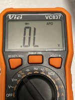
Edited to add - I have one type of DMM where the actual switch position can be for resistance, continuity, or diode check based on a push button selector. Make sure you don't have your DMM set to diode check, or it will likely light up the LED and not give you what you want. That's my final guess. 😀 Pic added to show one of mine in the wrong setting.
Make sure you are reading your DMM properly and/or take a picture of the way you're measuring the resistors and the meter during measurement. For many DMMs it will show a small designation for kilo or mega on the display.
With these boards it would be odd to short the resistors (but it could happen), but a 10 ohm instead of 10k ohm could be part of what you're seeing. Still odd that your DMM would put out enough voltage to light them even w/o a dropping resistor. If you have a spare LED, just set your meter to continuity and touch the probes to the legs (flip it just to be sure you cover both orientations if you're not sure). Then you'll at least know if your DMM puts out enough voltage to light the LED by itself. Then you can verify that you've got an appropriate resistor in place and move on from there.
Perhaps you had the caps populated and they charged?. Don't forget to post the other pics Ben had suggested.
Edited to add - I have one type of DMM where the actual switch position can be for resistance, continuity, or diode check based on a push button selector. Make sure you don't have your DMM set to diode check, or it will likely light up the LED and not give you what you want. That's my final guess. 😀 Pic added to show one of mine in the wrong setting.
Attachments
Last edited:
- Home
- Amplifiers
- Power Supplies
- diyAudio Power Supply Circuit Board v3 illustrated build guide